Using a 3 cent micro as a motor controller for a salvaged motor
How I put a recycled printer DC motor together with one of the cheapest chips in the world to make an intelligent DC motor.

The most salvagable part of A DC motor typically just spins when you apply voltage to it. But when you carefully control that voltage, and have access to an encoder attached to the motor, you can add some intelligence to the motor and do some very interesting things with it: like making it go to a precise position.
And combining that with one of the cheapest microcontrollers in the world makes it a little more fun, because now you can add a digital interface to the motor that allows any other modern microcontroller to easily command the motor for the cost of a single piece of tissue paper.
Investigating the motor
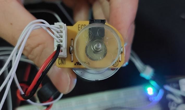
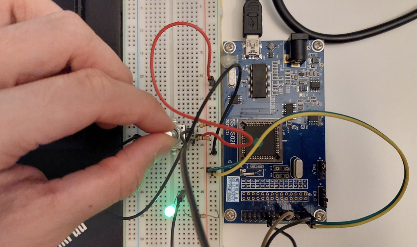
I recently had the opportunity to take apart an inkjet printer and out of it came several motors, one of which looked pretty interesting.
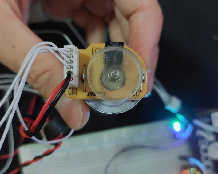
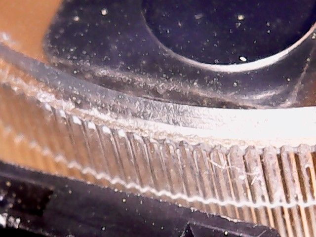
I thought this was pretty clever to use the ridges on a plastic cap as the 'disk' for the encoder. My guess is that it uses the refraction of the ridge to dissipate the signal from the LED to the optical sensor, thereby serving as the slots in a more conventional disk-based encoder.
When I started my investigation, I was pretty convinced that it was a single opto-isolator because I wasn't getting any of the results I was expecting.
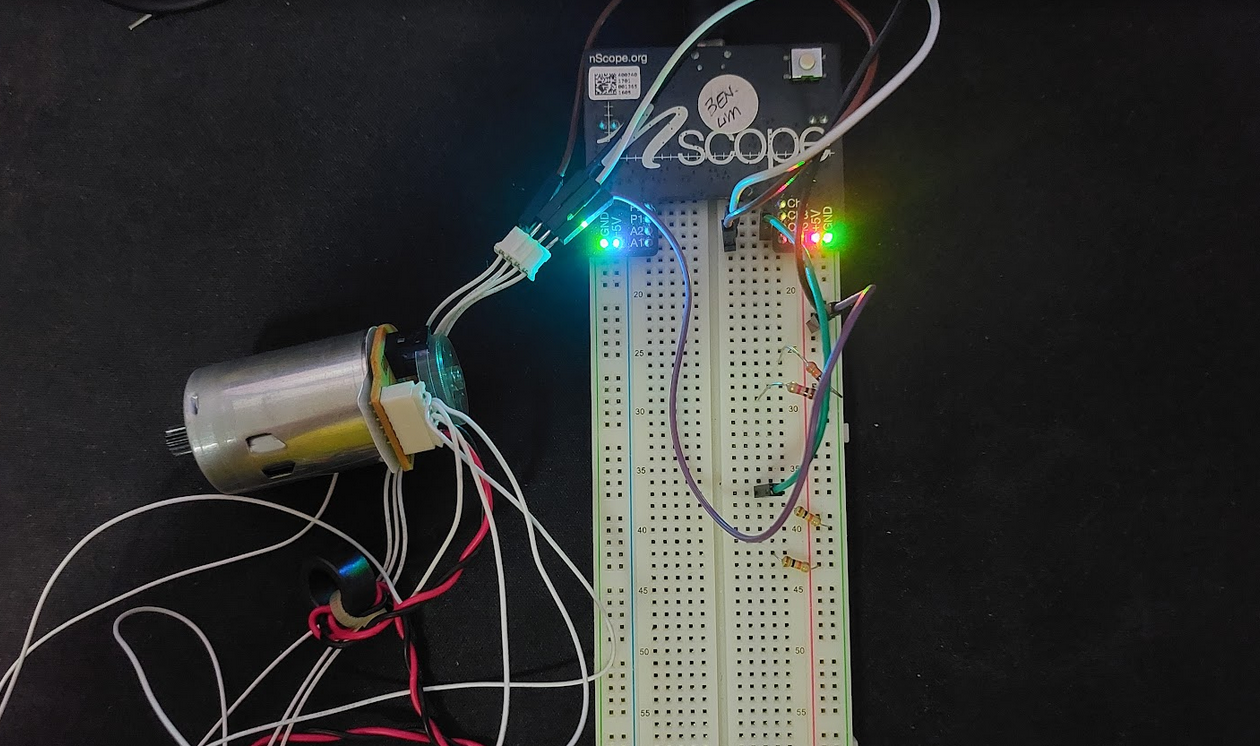
I plugged it into the nScope to read the signals, and after some experimentation (read: randomly plugging in wires) I was able to get something resembling a quadrature encoder readout. Success! Well partial success. While Ch1 responded, Ch2 (the flatish green line) remained stubbornly at a constant level.
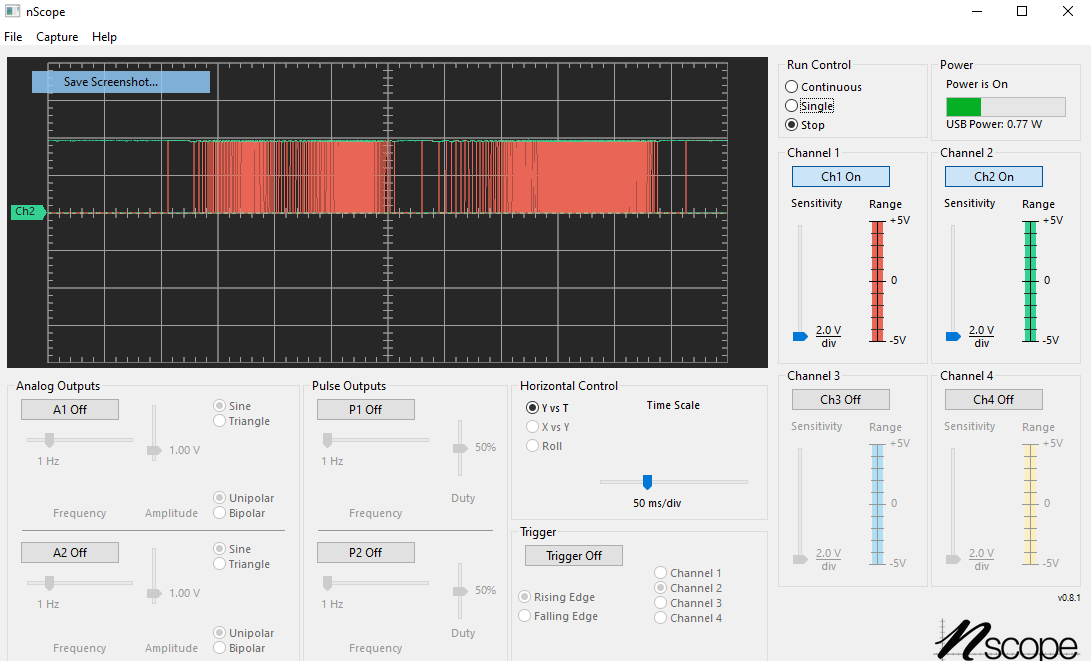
I noticed that if I zoomed in far enough, Ch2 on the scope exhibited some characteristics of a quadrature encoder, going from low to high, only that the signal is so attenuated to be barely visible.
So I decided to measure the resistance of the board I pulled the motor from.
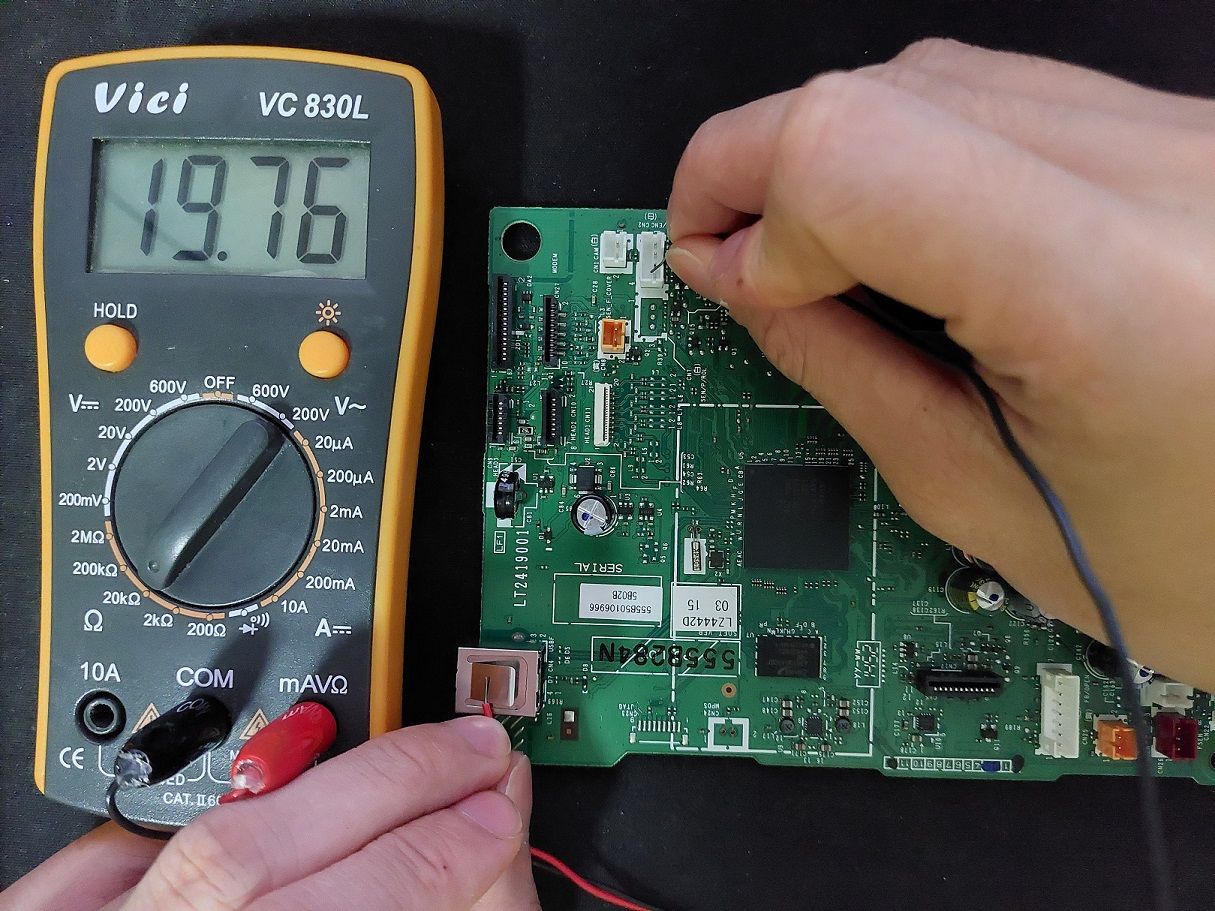
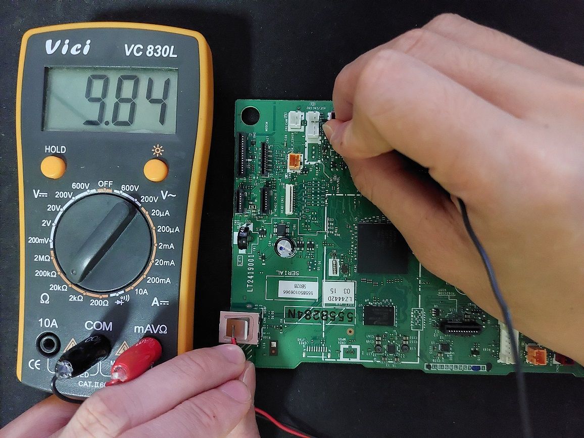
The pins that had the same resistance gave a hint of which pins where actually the sensor pins. Why? Well they would probably have the same pull-up resistors.
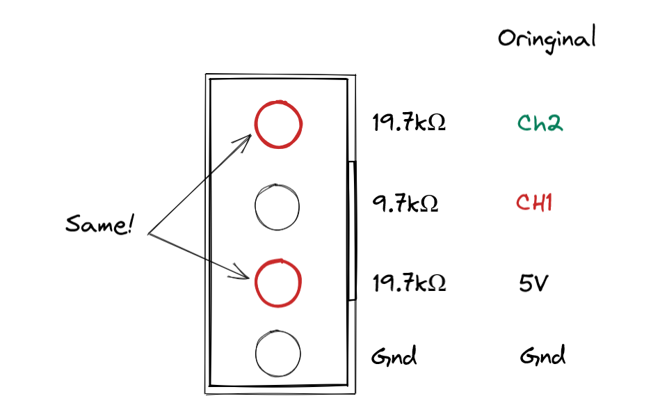
So I swapped the pins on CH1 and 5V and to my great delight it started to work perfectly.
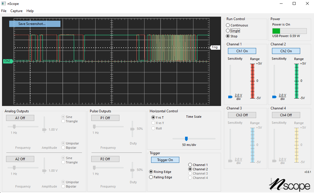
The voltage transitions are quite clean, which indicates to me that there is some sort of amplification going on to convert the analog signal from the optical sensors to a clean digital output.
Motor
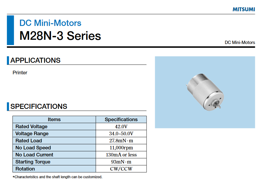
Taking a deeper dive into the motor, the voltage required by the motor (42V) is quite high and not typically available. My power supply goes up to 30V. After some investigation, I found other models of the same motor that have different nominal voltages.
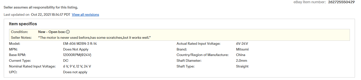
Since I am unable to find the original datasheet for my motor, I decided to pick 12V as the input voltage and tested it on my power supply, it drew way less than 130mA for it's no-load current so it is safe. Checking the power supply of the printer, I see that it only goes up to 31V, making it quite unlikely the motor is boosted to 42V.
I used a MAX14870 motor driver to drive the motor. It has exposes pins which allows the microcontroller to control both the direction and speed of the motor.
Programming
I am repurposing the Padauk PFS173 encoder IC that I made for the light controller because it uses the same principles with the addition of some motor control logic. If you have not read that, it provides a great intro into encoders and what this Padauk IC is all about:
If you are interested in Padauk ICs, which are known as some of the cheapest ICs in single quantities you can get your hands on, check out my original investigation:
The motor works in two modes: relative and absolute mode. In relative mode, the motor doesn't remember its position and receives a command over SPI to move either forwards or reverse from its current position. In absolute mode, it tracks its current position and the user sets a desired position.
While there is no dedicated SPI hardware on the IC, Padauk provides templates for various communication protocols in their IDE, so all you have to do is to copy and paste the template into the code you are using.
// SPI is configured in slave mode

static	void	SPI_Send (void)
{
	BYTE	cnt;
	BYTE	SPI_Data_Out;

	SPI_Data_Out	=	A;
	cnt	=	8;

	do
	{
		.wait1	SPI_Clk;      		// wait for SPI CLK to go to 1, for a single series FPPA, this is replaced by a instruction to go back
		sl		SPI_Data_Out;       // shift left 1 bit for SPI_DATA Out into C
		.wait0	SPI_Clk;			// wait for SPI CLK to go to 0
		.swapc_o SPI_Out;           // set SPI_OUT to the C register value
	} while (--cnt);
}
The additional work required adding in a simple PID motor controller, as well as tuning the code slightly to make sure it worked well with the motor I was using. Finally, I also wrote up some code to interactively control the motor using an Arduino Uno over SPI as it can be seen in the video above.
 benlhy
Board
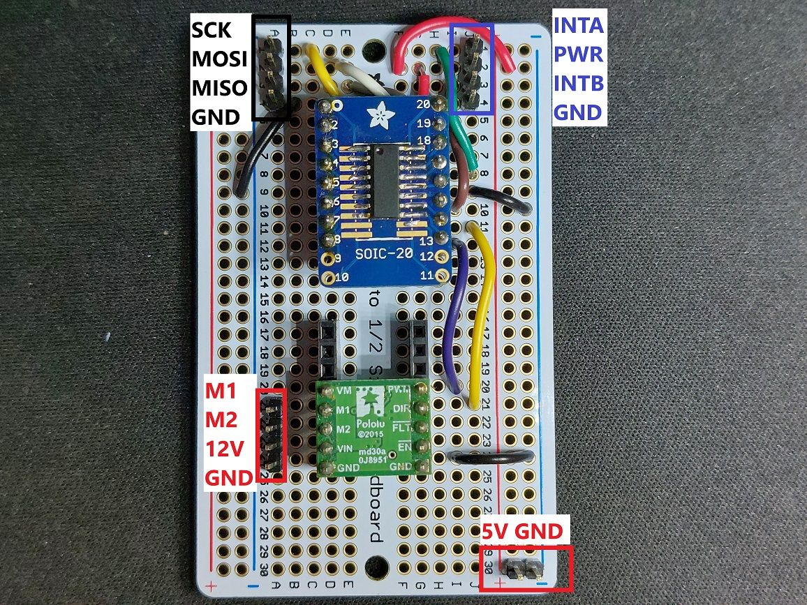
I soldered up a quick prototype board largely for my personal reference. Soldering through-hole parts on female headers increases the height, but also makes it easier to route and check connections since you can remove or replace the breakout board. It also eliminates the possibility of wires coming loose.
Conclusion
It works! I'm happy with where it is currently, and I have a few ideas on where it might be used. The key benefit is that I can use this with any DC motor with an encoder to obtain position control, and this method is arguably cheaper and simpler than using a stepper motor. It also helps to offload the processing for the encoder, allowing the core processor to focus on critical tasks.
For now I consider this as a milestone to mark this mini project complete and I'm looking forward to using it in my next project.
Stay tuned!