Using the 3 cent microcontroller as a encoder counter
Making a rotatory encoder counter in under a dime.

Even in the world of microcontrollers, a $0.03 microcontroller in single units is an oddity. It is very cheap. The cheapest microcontrollers you can find in single units among online distributors like Digikey or Mouser are in the region of $1. To push it below the $1 mark, your order usually has to be in the thousands. Putting it into perspective, it is a no-name smartphone for $6 in a world of $600 smartphones.
Is it great? Heck no. It uses an esoteric implementation of C called mini-C, documentation is all over the place, and the ICs are hard to source. But is it fun to use? That depends on your idea of fun. I like constraints and asking myself: "Now what can I do with this?"
I looked at these ICs a few years ago and poked around a little, exploring what it can be used. Since then, there is better documentation in the IDE, the ICs cost 4x more(!) and the open source toolchain (SDCC) has become more mature.
This time around I want to use this IC as an encoder counter.
Counting Signals
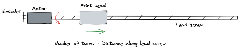
Keeping track of encoder counts is an important activity. Encoders are frequently used to keep track of the angular position, and that information is used to keep track of things like how fast a wheel is spinning or how far the print head of a printer has advanced.
However, encoder counting is also notoriously busy. Imagine that you had to stare at a screen that displayed two variables of either one or zero. By keeping track of how often the one or zeros appear and in which order, you can tell the position of the encoder and the direction it is turning. You can stare at the screen all day, which means you can't do anything else... or you could set up a notification to tell you when each variable has changed.
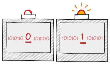
Instead of notifications, microcontrollers use interrupts to make sure that they don't miss counts. But with hundreds of counts a second, you might not be able to do anything else other than to service the interrupt, which is why some (read: expensive) chips have dedicated encoder modules, which freeing up the main controller to do other things like reading a control signal or sending out data.
Not all microcontrollers have this module and this is where the Padauk microcontroller comes in.
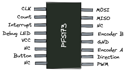
I/O
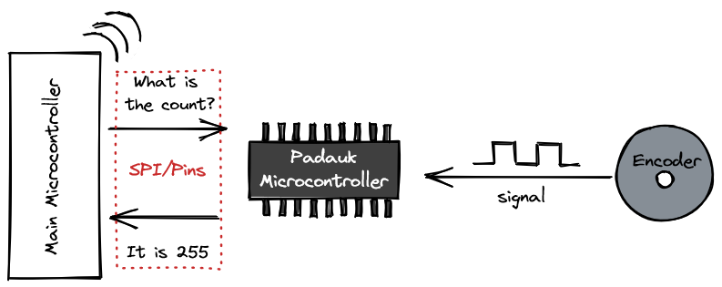
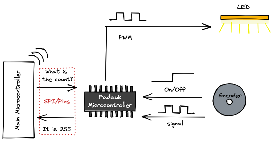
The concept is quite simple: use the Padauk microcontroller to do the busywork of reading the encoder, and then provide an easy means for another microcontroller to access the counts.
I decided on having two ways to read the count. SPI to get the exact count from the microcontroller, as well as a 2 pin count/dir control scheme for less position-critical applications: the Padauk microcontroller will output a pulse over one pin when it detects the encoder turning, and indicate the direction of the encoder using the other pin.
How a Rotary Encoder works
Rotary encoders work by outputting gray code. It is a pair of signals that indicate the number of turns, as well as the direction of the knob.
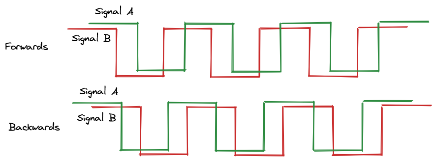
By reading when each signal changes and keeping track of which signal changes first, the count on the encoder can be accurately incremented or decremented.
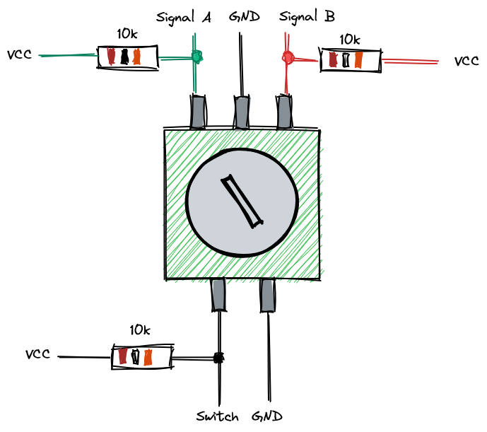
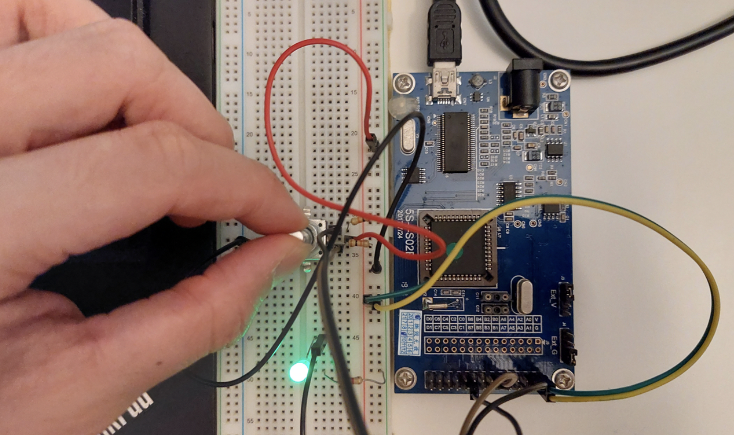
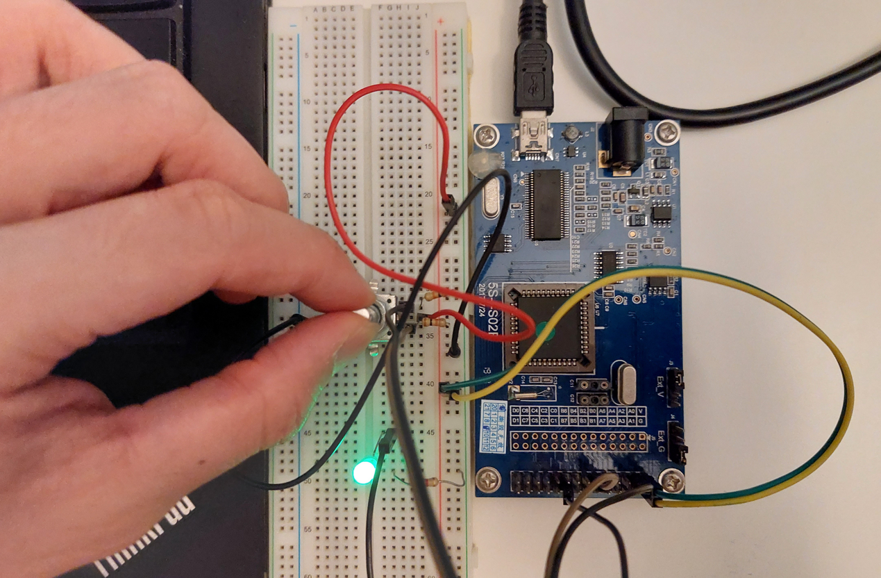
The wiring for the encoder is also fairly simple, with pull-up resistors on each channel.
Coding
Emulating the IC
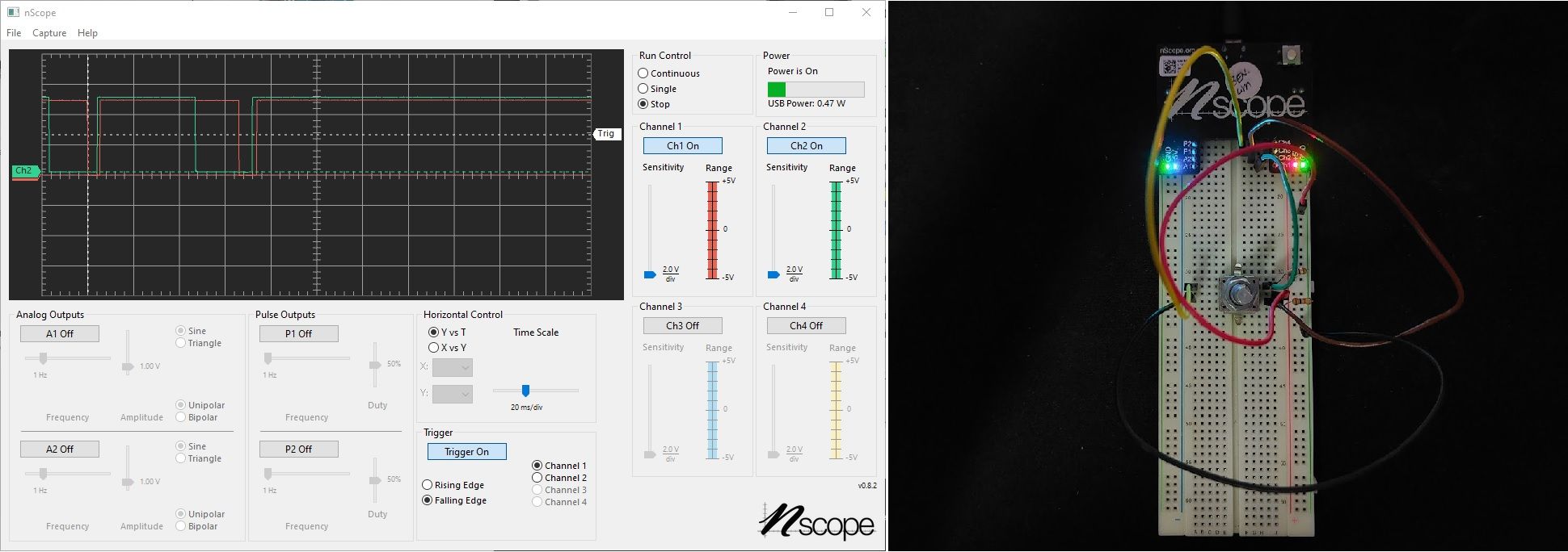
I tested the code on the emulator from Padauk. I found the debugging experience to be quite useful in fixing a few errors in my logic. The Padauk IDE automatically displays all the registers and their current state as well as the values of variables in each part of the code as you step through.
Because the instruction set for the Padauk ICs is so small, it is possible to display everything on the IDE. One thing I didn't like was that the documentation for Mini-C is split across the Application Note in the IDE as well as in the datasheet of the IC.
In the code I set up two interrupts to read the gray code from the encoder and to store it to a global variable. This global variable can be incremented and decremented.
Two's complement
Mini-C doesn't have the concept of negative numbers which is usually implemented as two's complement.
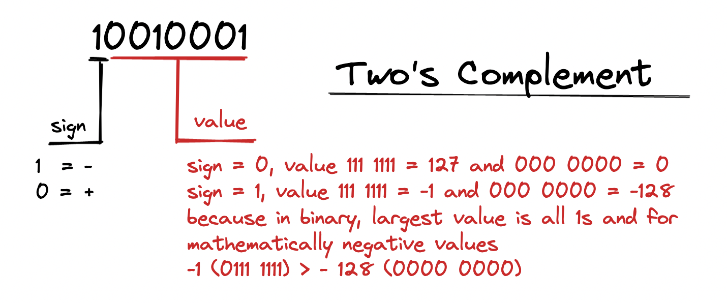
This method is consistent with the logic of binary and arithmetic operations so it is a really useful way of representing negative numbers. However in lieu of not needing to have negative values since I'm more interested in the relative position of the encoder, another way to achieve this is to initialize the value in the middle of the range.
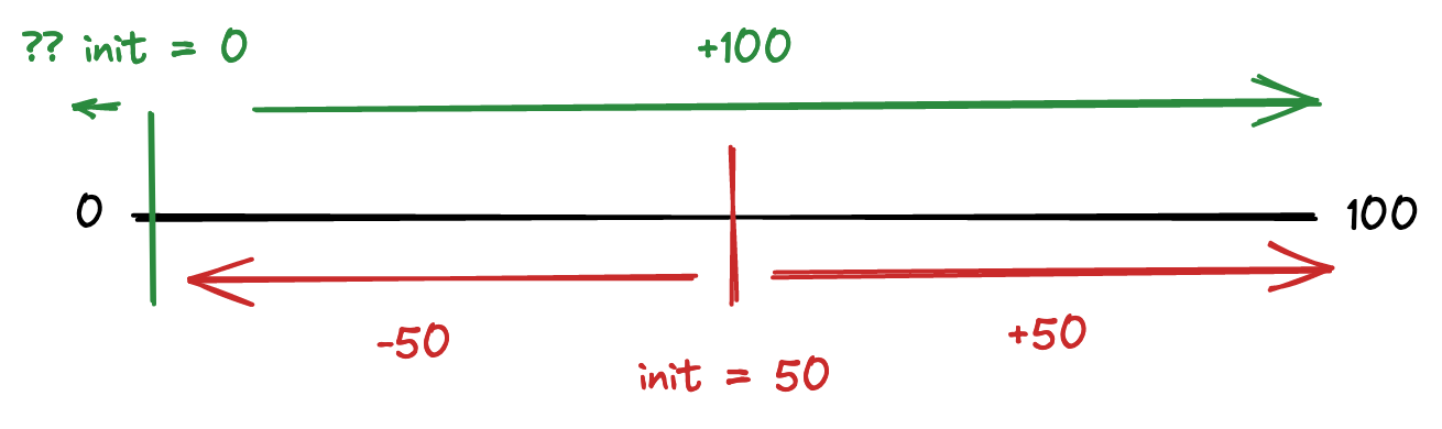
If we start at zero and don't implement two's compliment, the value will roll around from 0 back to 100, which is undesirable. Instead, I started the value in the middle of the range, and this allows it to decrement and increment normally. All I have to do is to keep track of the initial value and reset it before it rolls over.
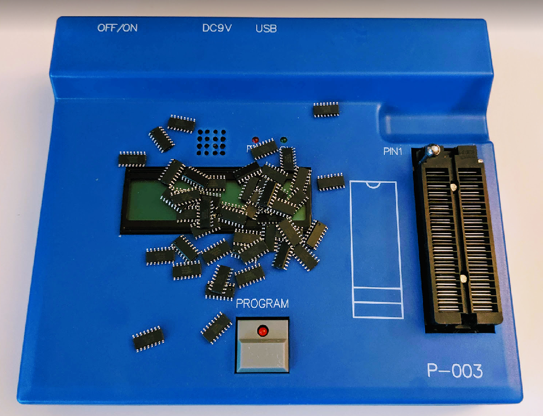
Programming the IC
When you hit Program, Padauk's programmer saves the binary to the memory of the programmer so you can use it as a standalone device or trigger the download process from the computer.
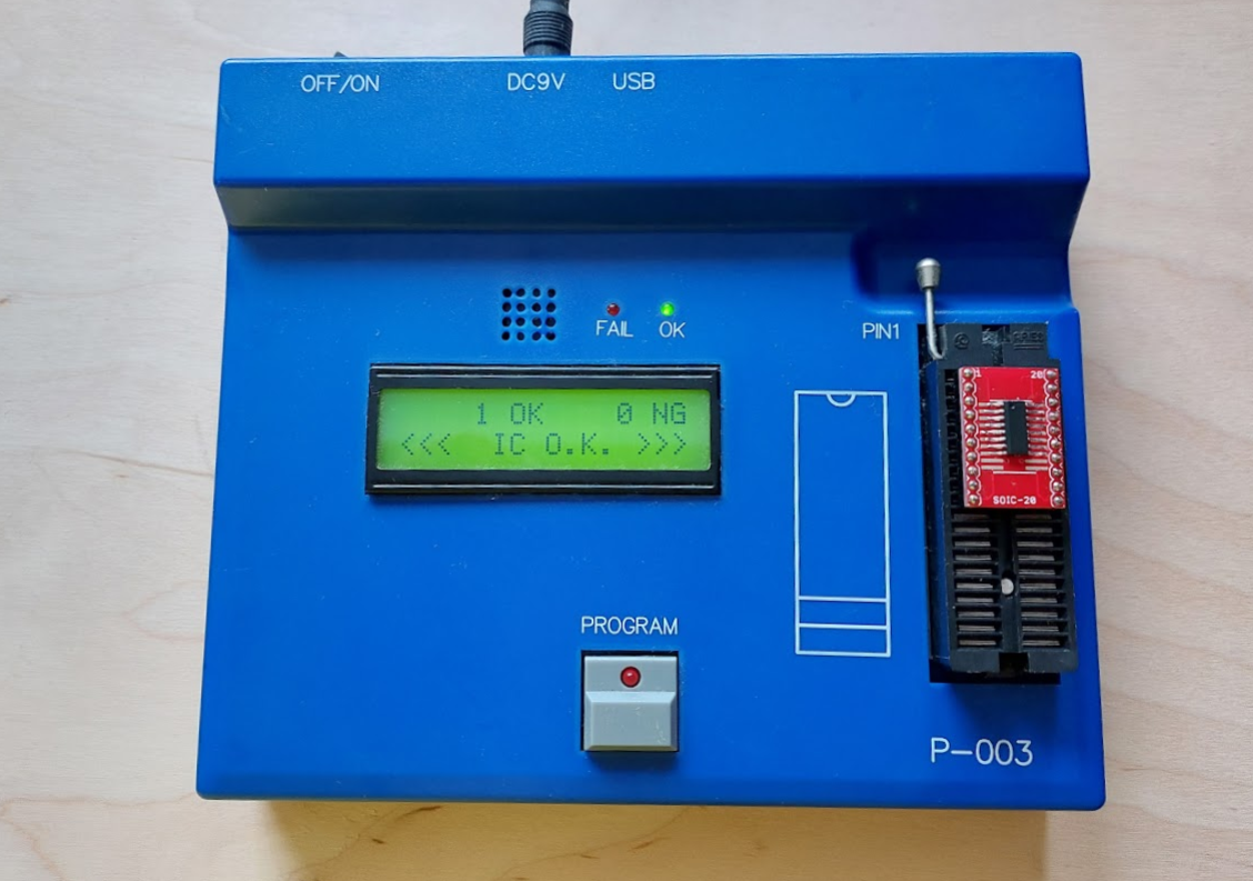
The PFS173 that I was using supports Multiple Time Programming (MTP) and it does what it says on the lid, it allows it to be programmed multiple times. There are other Padauk ICs can only be programmed once such as the PMC150.
Putting everything together
Along the way, I added a few other functionalities, such as the ability for the board to serve as the main controller instead of just interpreting the encoder signals as well as being able to save the last set PWM value when it turned off or on. When I was reasonably happy with the result, I moved it to a dedicated board on my main project.
Thoughts
In total it took me about two days to familiarize myself with the functionality and to debug the code. With regular use, programming the IC and soldering it could be shortened to a few hours.
For me, having this ultra-cheap microcontroller around is pretty useful as a general purpose IC that can take the place of more specialized components or devices. I like it because it is cheap, easy to solder, and is easy to understand and program.
If you enjoyed this article, please consider signing up for the newsletter and get in touch with me!
Additional observations
Documentation
The documentation has improved since the last time I looked at it. Now there are proper sections and categories that are clearly segmented and there aren't any broken links. The language has also been cleaned up since the last time. I checked the Mandarin version of the software and documentation and I didn't find any differences. I do still wish for better documentation on Mini-C however.
SDCC
Small Device C Compiler is now more mature and supports a wide variety of Padauk ICs. However, you'll still need to build the programmer yourself and there is no emulator. The benefit is that you get access to modern C, which is definitely better than the esoteric mini-C that Padauk implements. If you don't have a Windows device, that is probably also the only way you can program these ICs.
I still personally like using Padauk's IDE and mini-C because I find that they work well enough for my purposes. Being able to step through the code is still enormously useful for me and I don't fancy swapping the microcontroller from the board to the debugger and vice-versa for each update of the code
Cost
Padauk ICs now cost almost 4x as much from the time I bought them in 2019.
The programmer is powered by default
I dropped the IC into the writer while it was powered, thinking that it would survive hot-plugging since I haven't hit the program button yet. Boy was I wrong. It fried the IC because it was slanted when I inserted it in - the wrong pins were connected and I spent a few long minutes trying to figure out why it wasn't working before I decided to try another IC, this time carefully positioned before I plugged it into the Writer. It worked on the first go.
Surprisingly smart compiler
The compiler errors out when it detects certain structures of code that lead to ambiguity which I've not seen too often. For example, if you have a if-else statement that is triggered when a value is >0, then the compiler will not accept a else if statement because that would be ambiguous. It wants only an else statement: if you've already covered everything from 0 but not zero, then the only other option is zero. Having if-else would imply that there are at least two more outcomes, which the compiler regards as logically impossible and so declines to compile.