Padauk Microcontrollers: Exploration and Usage
Exploring the 3 cent microcontroller from Padauk, Taiwan. Impression: A legitimate replacement for simple use-case projects.

Exploring and using the 3 cent microcontroller. Impression: A legitimate replacement for simple use-case projects.
Idly I decided to research what is the cheapest microcontroller you can get and develop with, and I came across a Hackaday post regarding precisely this topic. Tim from [coldcpu] has put in a decent effort at categorizing the cheapest microcontrollers available, along with their associated pros and cons. In another separate Hackaday post, someone used a Padauk microcontroller to bit-bang the WS2812b protocol.
This led me down the rabbit hole where I had some fun watching Dave of EEVblog fame evaluate these microcontrollers over a series of videos. He seemed to have a positive opinion on them. There is also some work that has been done through the EEVblog forums on creating an open source compiler for the Padauk in the Small Device C Compiler (SDCC). It was fun reading for awhile, but my enthusiasm was dampened somewhat when I realized that I needed to build my own programmer. Added to that was the realization that there would not be an easy way to debug these microcontrollers through SDCC since it does not support the In Circuit Emulator (ICE) for Padauk.
However, when merely days later, the author of The Amazing $1 Microcontroller, Jay Clarson published an in depth look at these microcontrollers, my interest was rekindled and I decided to give these microcontrollers a spin.
 benlhy
First Impressions
After playing around with these microcontrollers for awhile, I find that these low cost multipurpose chips are excellent for projects where all you need is to toggle a pin or take an input. You can use them as protocol decoders, GPIO expanders, motor controllers, logic ICs... the list goes on. Think of this as the stem cell for all your logic requirements. Anything where you don't need a ton of space, memory, or speed, this is the IC for you.
So why use this chip over say something like an EFM8 or a STM32? Well for starters you can get these in SOT-16 packages, which makes them reasonably easy to hand solder. And why over something like PIC16? A PIC would cost about 20 times as much, and with a Padauk, I don't even have to think to plonk it down in a build for testing. If it works out, great! If it doesn't, no great loss.
Below I will give a more detailed overview on how these chips can be obtained and used. In the last section I will also provide some example code to get started with.
If you want to get started exploring the material, Padauk's website and documentation is all available in English.
IDE
The install process for the IDE was a little... abrupt. There is no option to chose anything, and instead, it just unpacked the files directly to the C:\ drive in my computer.
I admit that when I first opened the IDE I felt that it looked old and kind of clunky. The font was jarring at first, but it has begun to grow on me. It is easy to read and reminds me of old-school command lines.
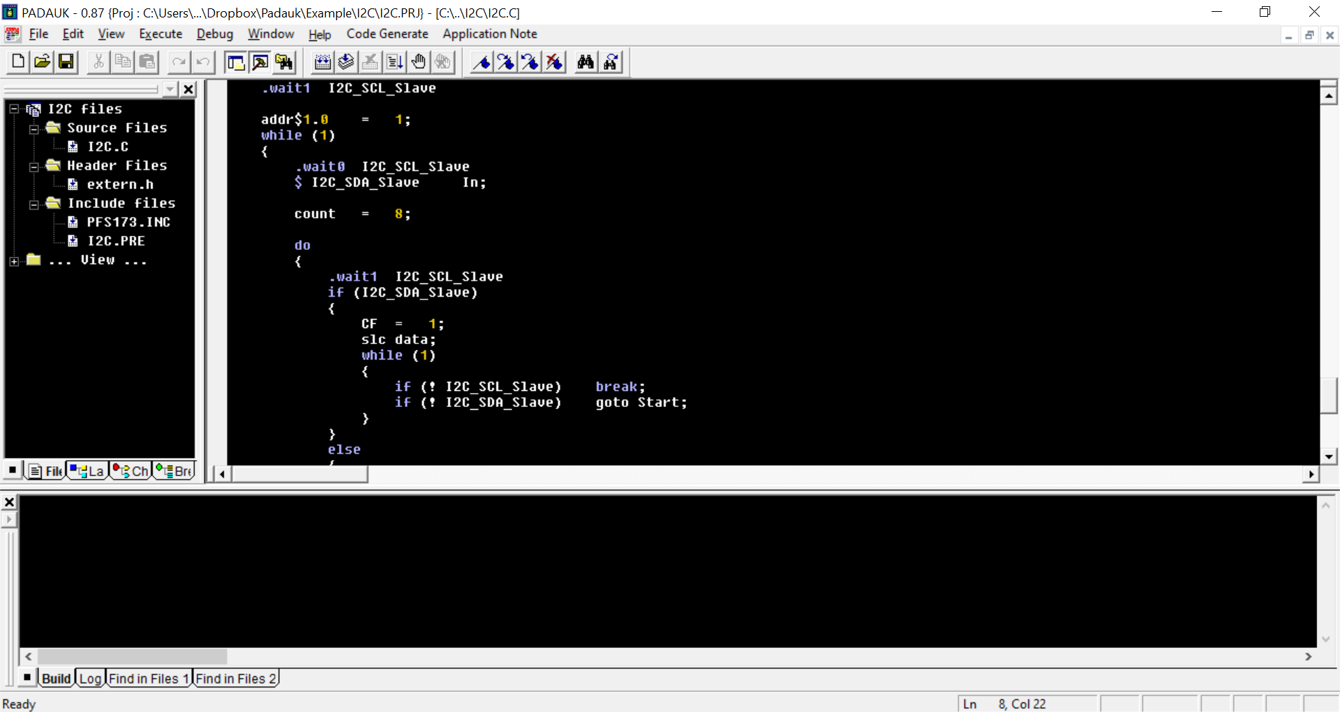
I have also come to appreciate the IDE a lot. It starts quickly and every option has a purpose. It feels like someone actually went through and removed all the extraneous options. It continues immediately where I left off. Opening new projects is a snap, and switching views is really quick. It might have to do with it being a 30MB download. Project files are easy to replicate and there's none of that nonsense about having to create the project in the IDE itself before it can be recognized as a valid project (looking at you Atmel Studio). It integrates flawlessly with the programmer and the ICE and I had no issues running it.
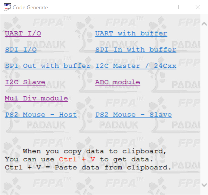
Code Generate Tool
The Padauk IDE helps you to generate code for the various communication peripherals as the ICs do not have these as hardware peripherals. This can be both a curse and a blessing. On one hand there isn't a 100 page pdf of registers to work through to configure, on the other hand you have to spend cycles, memory, and power to implement UART, I$^2$C, and SPI.
I found the example code to be quite helpful and useful, although I struggled with trying to understand the I$^2$C code with it's goto-s.
Application Code
[Sep 2020] The documentation has been considerably updated and tidied up, with many missing articles being added and organized.
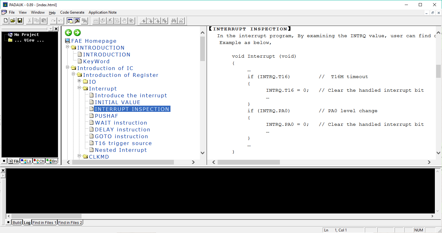
[outdated] This is where I have to take off points. The information provided here is a jumbled mess and some links are missing. I wish this section was cleaned up because it has such good potential as a guide to using Padauk ICs, especially those who haven't had a chance to use them before. However, frequently you can find some enlightening parts about the logic behind Mini-C.
Datasheet
The datasheet has also been cleaned up considerably since the last time I looked, and all the missing sections have been included. The datasheet is quite helpful in providing hints on how to get various peripherals working. It also provides some example code so definitely check the datasheet out if you are having some trouble implementing certain aspects of the code.
Software Support
There is no software support of any type. There are no forums to post questions or get answers from. The error messages in the IDE can be quite cryptic as well. Sometimes adding a space will break the code (don't change the auto-generated code), even though technically, C is not a whitespace-based syntax.
In my experience, using both the application documentation in the IDE as well as the documentation in the datasheet was sufficient to keep me going. I found that register programming here is pretty rewarding as compared to some of the larger microcontrollers because there are a smaller number of registers to use, mainly because you don't have to configure communication peripherals.
The support you can get through email is surprisingly good for sourcing information and they got back to me within a day when I had a few questions on the QFN versions of these chips. Answer: there is only one supplier selling one QFN version of these ICs, so don't expect to be able to get QFN ICs unless you need huge quantities of these ICs. However, they were less able to help with my questions on firmware development.
Hardware Line-up
Padauk mostly manufactures One Time Programmable (OTP) parts, although there some Multiple Time Programmable (MTP) ICs. This distribution of parts makes sense in the context where you are manufacturing a million of these parts and are only programming them once. It saves on having to dedicate a few pins to programming and debugging, and it probably also costs less as well.
The development framework for Padauk is that you design and debug the circuit with the In Circuit Emulator (ICE) and when it is time to transfer it onto a PCB you load the programmer with the firmware and then program each OTP IC once. Ideally, the IC would work as well as using the ICE, as it should emulate each IC correctly.
Padauk offers these ICs mostly in the SOT form factor. The QFN form factor is largely unavailable through distributors and probably only available through direct requests.
ROM ranges from 1k to 4k words, and RAM ranges from 16 to 256 bytes.
Where can I buy these microcontrollers?
From the manufacturer's website:
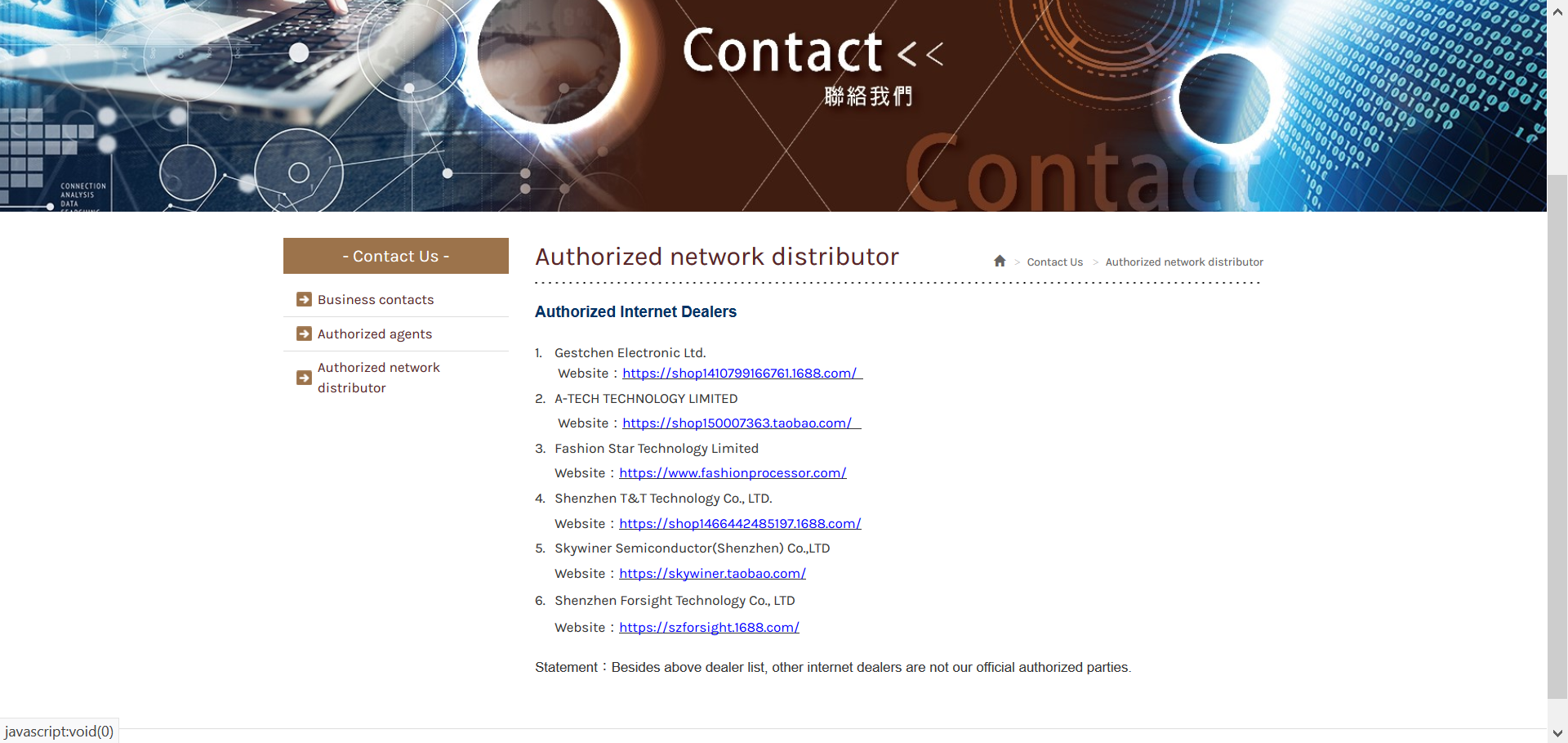
This page lists the authorized distributors. The only problem is that a lot of these distributors are from the 1688, which only caters to customers in China. An alternative is to source from Taobao, and there are more sellers for Padauk parts than what is listed here on the website. However, Taobao can be quite a hassle to ship from, especially if you can't read Mandarin, and the shipping is expensive if you are shipping small quantities.
Another alternative is to buy from LCSC, a Chinese version of Digikey and Mouser. While they are not listed as an authorized distributor, in my experience, LCSC is the best choice for getting the programmer and In Circuit Emulator (ICE) for Padauk because the website options are in English and they provide fairly good options when it comes to shipping. I didn't know about this until recently, but LCSC also gives you a pretty steep discount on shipping if you order PCBs and components. While the programmers and ICEs usually listed as not in stock, you can get a quotation from LCSC in a day and they are happy to source it for you. Having wrangled with shipping from Taobao, I think this might be the best method for obtaining Padauk programmers and emulators for now. I found the prices to be quite similar to other sellers.
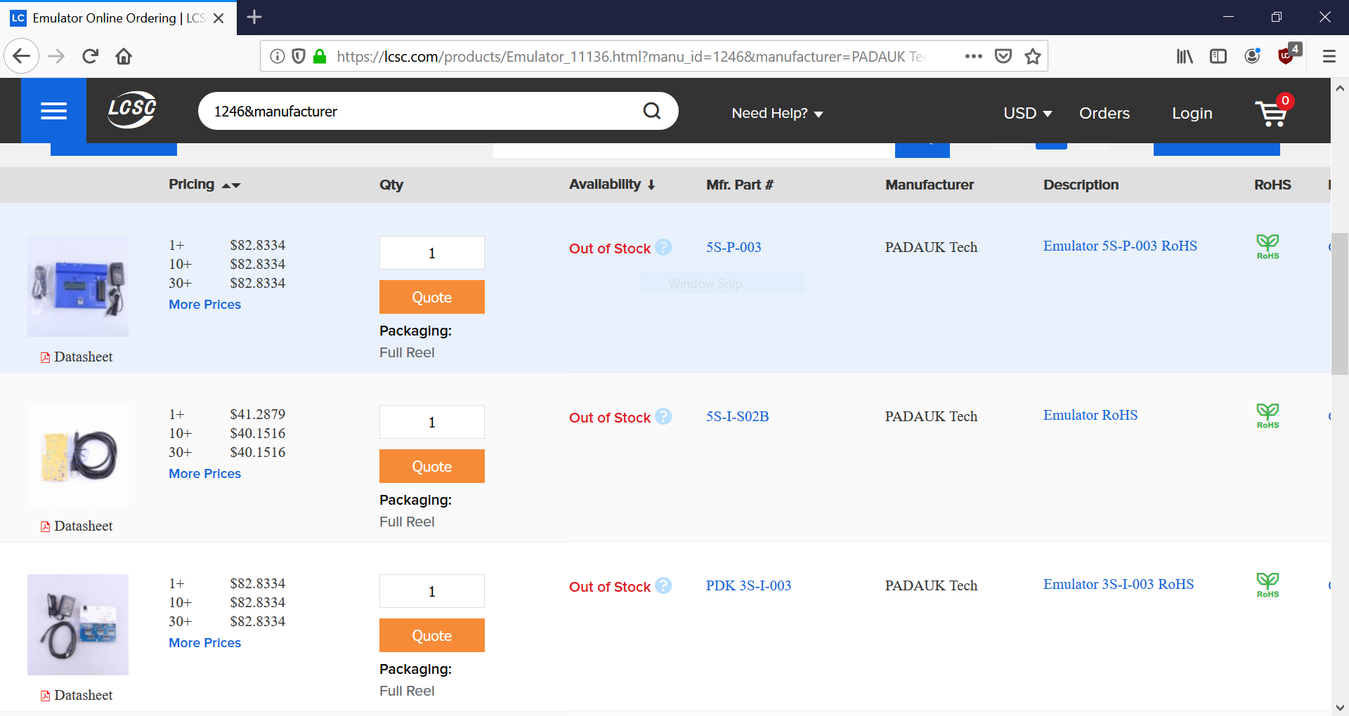
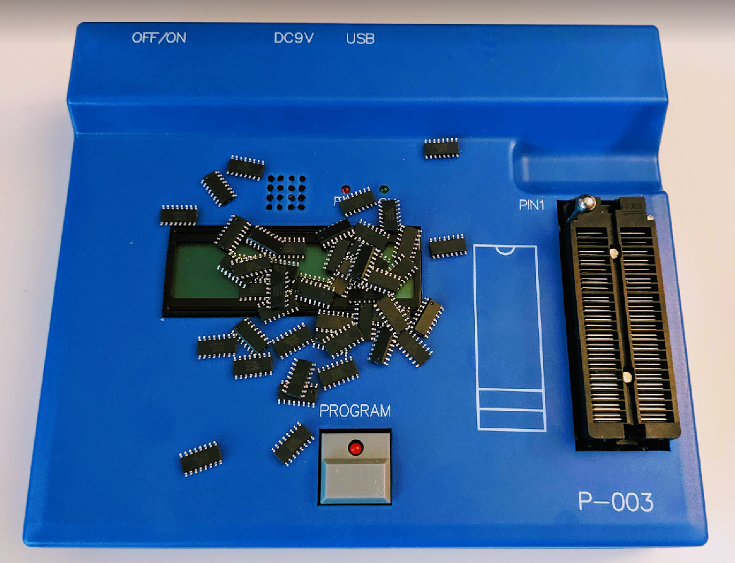
You will want to get the 5S-P-003 programmer and the 5S-I-02B emulator as these are the latest versions of their respective types.
Programming Experience
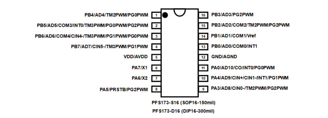
I first got the programmer and sourced two different ICs: PFS173 ($0.08) that can be reprogrammed multiple times, and the original 3 cent microcontroller, the PMS150c.
The programmer came with a 16 pin SMT test socket so I was able to program the SOT versions of these chips. One really nice feature is that the IDE includes an 'OS detect' program that helps to detect what chip is being used. When I used the OS detect program, it indicated on the programmer that Pin16 was open, and I found that one of the headers on the SMT test socket was not soldered in correctly. Once I resolved that issue, everything worked smoothly.
Creating projects
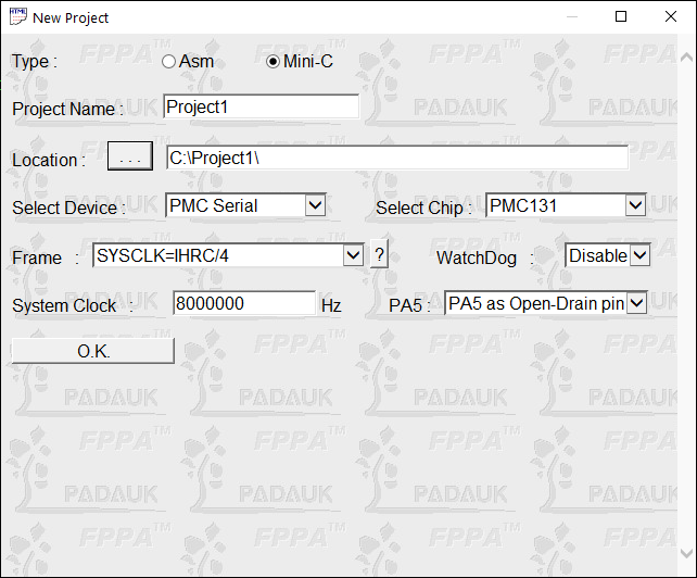
Each project has to be created within the new project dialog so that it sets up the project correctly for you. For most cases, you'd want to make sure that you select Mini-C, and set the device correctly.
Programmer
The programmer makes a really loud beep when programming has failed and it really startled me when it first happened. But I guess it makes sense on a noisy factory floor. There is also a large green blinking CHECK? that appears in the top right of the Writer program. If that is the case, check to make sure all connections are correct and connected. If programming is successful, a blue PASS will flash instead.
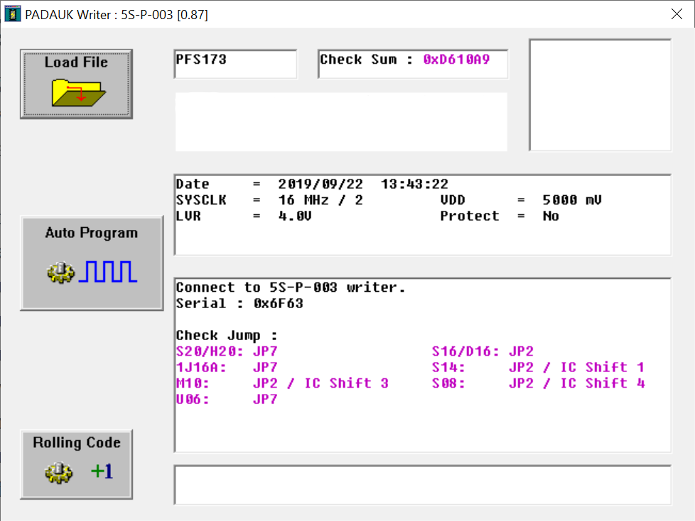
To program, click on the Auto Program button in the Writer. You can also press the Program button on the programmer itself once you have uploaded the most recent .pdk file onto the programmer.
The progammer also indicates to you how you should connect your IC. On the back of the programmer are a series of jumpers that you can use. For example, if you are using a SOT16 IC, and in the writer window it says S16/D16: JP2 then you should check that all the rows on the JP2 header are connected on the back of the programmer. If you are using a SOT14 IC (S14: JP2 / IC Shift 1), then you should also connect your IC one space from the top of the ZIF socket on the programmer.
The programmer also compares its version against that on the computer, and the writer warns you if they are different. Loading the code onto the programmer is fast and you can use it independently of a computer. The programmer will display the expected IC, checksum, as well as the program name on the LCD.
Overall, I found the programmer very user friendly.
ICE
Padauk also provides an ICE that you can use to emulate their ICs for ease of development. This gives you access to a wide variety of chips that they have, albeit with some caveats that they list in their datasheets.
I found this an invaluable tool when developing with Padauk ICs.
Final Thoughts
I felt that this was a fun project to explore some of the cheapest ICs that you can get in single quantities and they are suprisingly quite capable. While you'll need something more robust for a wireless communication project, or something that interfaces with a lot of sensors, however, if all you are doing is reading a few inputs and reacting with some output signals, you could do much worse than Padauk microcontrollers.
Code Examples
I wrote some starter code if those are interested in getting started. This is written for the PFS173 microcontroller, which is the newest flash-based microcontroller in the Padauk lineup.
Simple GPIO
Toggle a LED when a button is pushed.
Configuration options: PA0: Input, PA3: Output
#include	"extern.h"

// PA0: Input, PA3: Output

void FPPA0 (void) {
	.ADJUST_IC SYSCLK=IHRC/2;
	PA = 0b_0000_0000; // Port A Data register
	PAC = 0b_1111_1110; // Port A Control register, 0/1: input/output
	PAPH = 0b_0000_0001; // Port A Pull-High Register 0/1: disable/enable
	$ PADIER 0b_1111_1001; // Port A Digital Input Enable Register, 1/0: enable/disable, Bit 2:1 is reserved
	while (1)
	{
       if( pa.0 == 0) {
			pa.3 = 1;
		} else {
			pa.3 = 0;
		}
//		...
//		wdreset;
	}
}
Output Demultiplexer
So just by having some control over the GPIO, we can expand this into a simple output demultiplexer. This gives you control (abit not simultaneous) over 8 additional pins for 3 output pins
#include	"extern.h"

// PA0: Input, PA3,PA4,PA5: selector input
// PB0~7: Output

void FPPA0 (void) {
	.ADJUST_IC SYSCLK=IHRC/2;
	PA = 0b_0000_0000; // Port A Data register
	PAC = 0b_1111_1111; // Port A Control register, 0/1: input/output
	PAPH = 0b_0000_0000; // Port A Pull-High Register 0/1: disable/enable
	PADIER =  0b_1111_1001; // Port A Digital Input Enable Register, 1/0: enable/disable, Bit 2:1 is reserved

    PB = 0b_0000_0000; // Port B Data register
	PBC = 0b_0000_0000; // Port B Control register, 0/1: input/output
	PAPH = 0b_0000_0000; // Port B Pull-High Register 0/1: disable/enable
	PADIER =  0b_1111_1111; // Port B Digital Input Enable Register, 1/0:

	while (1) {
       if( pa.0 == 0 && pa.3==0 && pa.4==0) {
			PB = 0b_0000_0001;
		}
        if (pa.0 == 0 && pa.3==0 && pa.4==1)  {
			PB = 0b_0000_0010;
		}
        if( pa.0 == 0 && pa.3==1 && pa.4==0) {
			PB = 0b_0000_0100;
		}
        if (pa.0 == 0 && pa.3==1 && pa.4==1)  {
			PB = 0b_0000_1000;
		}
        if( pa.0 == 1 && pa.3==0 && pa.4==0) {
			PB = 0b_0001_000;
		}
        if (pa.0 == 1 && pa.3==0 && pa.4==1)  {
			PB = 0b_0010_0000;
		}
        if( pa.0 == 1 && pa.3==1 && pa.4==0) {
			PB = 0b_0100_0000;
		}
        if (pa.0 == 1 && pa.3==1 && pa.4==1)  {
			PB = 0b_1000_0000;
		}

	}
}
Shift register
ADC with UART output
Read an ADC and output it over UART.
Configuration options: ADC: PB2, UART: PB0, PB1.
#include	"extern.h"

BYTE out;

FPPA_Duty		=>	_SYS(INC.FPPA_NUM);	// Single FPPA = 1, Mult FPPA = 2 or 4/8/...

Baud_Rate		=>	9600;
/*
UART_Delay		=>	(System_Clock / FPPA_Duty) / Baud_Rate;

	if	System_Clock	=	8,000.000 Hz
		FPPA_Duty		=	/16
	so	FPPA_Clock		=	System_Clock / FPPA_Duty	=	500.000	Hz

	if	Baud_Rate		=	19200
	so	UART_Delay		=	500.000 / 19200 = 26.0416...
	so	match, 26 cycles send one bit.	< 0.5%

	if	Baud_Rate		=	38400
	so	UART_Delay		=	500.000 / 38400 = 13.02083...
	so	match, 13 cycles send one bit.	< 0.5%

	if	Baud_Rate		=	56000
?	so	UART_Delay		=	500.000 / 56000 = 8.9285...		<	1.0%

	if	Baud_Rate		=	57600
X	so	UART_Delay		=	500.000 / 57600 = 8.6805...		:	fail
*/
UART_Delay		=>	( (System_Clock / FPPA_Duty) + (Baud_Rate/2) ) / Baud_Rate;
//	+ (Baud_Rate/2) : to round up or down

Test_V0			=>	System_Clock / 1000 * 995;
Test_V1			=>	UART_Delay * Baud_Rate * FPPA_Duty;
Test_V2			=>	System_Clock / 1000 * 1005;

#if	(Test_V1 < Test_V0) || (Test_V1 > Test_V2)
	.echo	%Test_V0 <= %Test_V1 <= %Test_V2
	.error	Baud_Rate do not match to System Clock
#endif

UART_Out		BIT	PB.0;
UART_In			BIT	PB.1;

static	void	UART_Send (void)
{
	BYTE	cnt;
	BYTE	UART_Data_Out;

	UART_Data_Out	=	out;

	//	Start Bit
	set0	UART_Out;				//	1

	#if	FPPA_Duty == 1
		cnt	=	8;						//	2 ~ 3
		.Delay	3;						//	4 ~ 6
		do
		{	//	Data Bit * 8
			.Delay	UART_Delay - 10;
			sr		UART_Data_Out;		//	7
			if (CF) {
				nop;					//	10
				UART_Out	=	1;		//	1
			} else {
				UART_Out	=	0;		//	1
				.delay	2;				//	2 ~ 3
			}
		} while (--cnt);				//	4 ~ 6
		.Delay	UART_Delay - 5;
	#else
		.Delay	UART_Delay - 4;
		cnt	=	8;						//	2 ~ 3

		//	Data Bit * 8
		do
		{
			sr		UART_Data_Out;		//	4		4
			swapc	UART_Out;			//			1
			.Delay	UART_Delay - 4;
		} while (--cnt);				//			2, 3

		.Delay	2;						//			3 ~ 4
	#endif

	//	Stop Bit
	set1	UART_Out;				//	1
	.Delay	2 * UART_Delay - 2;
}									//	2


void	FPPA0 (void)
{
	.ADJUST_IC	SYSCLK=IHRC/2;		//	SYSCLK=IHRC/2

	//	Insert Initial Code
	//  UART_HandShake();
	PBC = 0b_0000_0011; // Set PB0 ~ PB3 as Input
	PBPH = 0b_0000_0000; // Disable pull high register
	PBDIER = 0b_0000_0011; // Disable digital input for PB0 ~ PB3

	$ ADCC Enable,PB3; // Enable.
	$ ADCC Enable,PB2; // The $ indicates to the compiler that 'Enable' and 'PB2' are keywords and it should look in the inc file.


	$ ADCM /16; // For system clock 8Mhz as indicated in the datasheet, clock selection
	.Delay 8*400; // delay 400us, datasheet does not state why. Probably for the pins to be set up

	// .error Hey this is an error <- nice debugging tool
	// .echo Okay done here <- Another nice tool.


	while (1)
	{
		AD_START = 1; // This is a bit in the ADCC register, write 1 to start, read 1 to see if ADC is finished.
		while(!AD_DONE) NULL; // Because AD_Done is defined as it's own 'word', so we don't need to reference the ADCC register


		out = ADCR; // ADC conversion result, the accuracy of this device is 18 bits.

		UART_Send(); // send out the value. Note that this is essentially a uint8 value.
		.Delay 1000000; // don't want to flood the buffer of the receiving device.
//		...
//		wdreset;

	}
}
Simple PWM
This PWM counts from 0 to 100 using the hardware timer.
Configuration Options: PA0 output
#include	"extern.h"

void	FPPA0 (void)
{
	.ADJUST_IC	SYSCLK=IHRC/16, IHRC = 16MHz, VDD=5V;		//	SYSCLK=IHRC/2

	Byte duty = 60;
	Byte _duty = 100-duty;
	Byte increment = 1;

	PWMG0DTL = 0x00; //PWM0 Duty Value Low Register * You have to write to the low register first [2:1]
	PWMG0DTH = _duty; //PWM0 Duty Value HIGH Register [10:3]
	PWMGCUBL = 0x00; //PWM0 Counter Upper Bound Low Register, Bits 2:1
	PWMGCUBH = 100; //PWM0 Count Upper Bound High Register, Bits 10:3

	$ PWMG0C Enable,Inverse,PA0;
	$ PWMGCLK Enable,/1,SYSCLK;

	while (1)

	{
		PWMG0DTL = 0x00;
		PWMG0DTH = duty;

		if (duty==100)
		{
			duty=100;
			increment=-1;
		}
		else if(duty==0) // it cannot compare negative values.
		{
			duty=0;
			increment=1;
		}
		else
		{
			nop;
		}
		duty = duty + increment;
		.delay 10000;

	}
}
Interrupts
This example toggles the LED based on the 16bit-timer
#include	"extern.h"

void	FPPA0 (void)
{
	.ADJUST_IC	SYSCLK=IHRC/4		//	SYSCLK=IHRC/4

	PA = 0b_0000_0000; // Port A Data register
	PAC = 0b_1111_1111; // Port A Control register, 0/1: input/output
	PAPH = 0b_0000_0000; // Port A Pull-High Register 0/1: disable/enable
	PADIER =  0b_1111_1001; // Port A Digital Input Enable Register, 1/0: enable/disable, Bit 2:1 is reserved

	T16M = 0b_0011_0111; // Timer 16 mode: clock:CLK, Pre-divider:+64, Interrupt: bit 15

	INTEN = 0b_0000_0100; // Enable the Timer 16 interrupt
	INTRQ = 0; // Clear the INTRQ register
    ENGINT;    // Enable global interrupts

	//	Insert Initial Code

	while (1)
	{

	}
}

// The name of the interrupt function is fixed and it will set the DISGINT   // (disable global interrupt) bit automatically when it enters the interrupt // function.

void Interrupt (void)
{
	pushaf; // Reserve the ALU and FLAG registers

	if (Intrq.T16)
	{	//	T16 Trig

		Intrq.T16	=	0; // clear the interrupt associated with 16-bit timer

		// does not do conversions from binary to values, i.e pa.3 = !pa.3 doesn't work

		if (pa.3 == 1) {
			pa.3 = 0;
		} else {
			pa.3 = 1;
		}
	}

	popaf; // Restore ALU and FLAG registers
}
With this functionality, we can emulate a shift register:
Configuration: PA0 - clock, PA3 - data, PA4 - latch
#include	"extern.h"

BYTE out;

void FPPA0 (void)
{
	.ADJUST_IC	SYSCLK=IHRC/16, IHRC = 16MHz, VDD=5V;		//	SYSCLK=IHRC/2

    PA = 0b_0000_0000; // Port A Data register
	PAC = 0b_1111_1111; // Port A Control register, 0/1: input/output
	PAPH = 0b_0000_0000; // Port A Pull-High Register 0/1: disable/enable
	PADIER =  0b_1111_1001; // Port A Digital Input Enable Register, 1/0: enable/disable, Bit 2:1 is reserved

	INTEN = 1; // Enable the PA0 interrupt
    INTRQ = 0; // Clear the INTRQ register
    ENGINT;    // Enable global interrupts


	while (1) {

	}
}

void Interrupt (void) {
  PUSHAF; // Reserve the ALU and FLAG registers
  if (INTRQ.PA0) {
    INTRQ.PA0 = 0 // clear the interrupt bit associated with PA0
    if (pa.3 == 0) {
      out = out<<1 || 0;
    } else {
      out = out<<1 || 1;
    }
  }

  POPAF;  // Restore ALU and FLAG registers

} // RETI (return from interrupt) is added automatically on compilation. It     // returns the code execution to the point in the main code where it was     // interrupted from.
Timers
#include "extern.h"

// OUTPUT PIN: PA3, this function will toggle the PA3 pin at a set frequency
// Freq = CLOCK / (2 x (K + 1) x S1 x (S2 + 1))
// K: Bound register
// S1: Prescalar, S2: scalar

void FPPA0(void) {
  .ADJUST_IC SYSCLK=IHRC/4;  //	SYSCLK=IHRC/4

  // Compressed syntax for LEDs

  BIT LED : PA.3;
  $ LED OUT;  // set PA3 as the output

  // Examine the .inc file for the syntax

  $ TM2C SYSCLK,PA3,PERIOD; // Clock: system clock, Output: PA3, mode: Period, polarity: do not inverse
  $ TM2S 8BIT,/64,/32;
  TM2B =  0b_0001_1111; // bound value: 127 (base value to reset timer x prescalars)
  //TM2C = 0b_0000_0000;

  while (1) {
  }
}