Simple Wireless Measurement Device
This is a wireless measurement device designed to measure the life of low-power circuits in IoT systems. It pairs with a companion device that allows accurate time-series measurement of power performance.

How I built a great tool for IoT prototyping: a self-powered, wireless measurement device that measures voltage and current.
 benlhy
The Gist
IoT devices have two big constraints: they are wireless, which draws power, and they are often battery powered, which means that they don't have much power to draw upon. Managing the power draw then becomes an important feature in any IoT project. I built a device that can help me do exactly that.
This is a self-contained, compact wireless device that can be embedded in other devices for electronics prototyping and design. It does two things very well: measure voltage and current, which is useful when you want to do a time-series recording of devices. It can measure down to a resolution of 1.2 uA and 60 mV.
Each part of this project is built upon something I developed earlier:
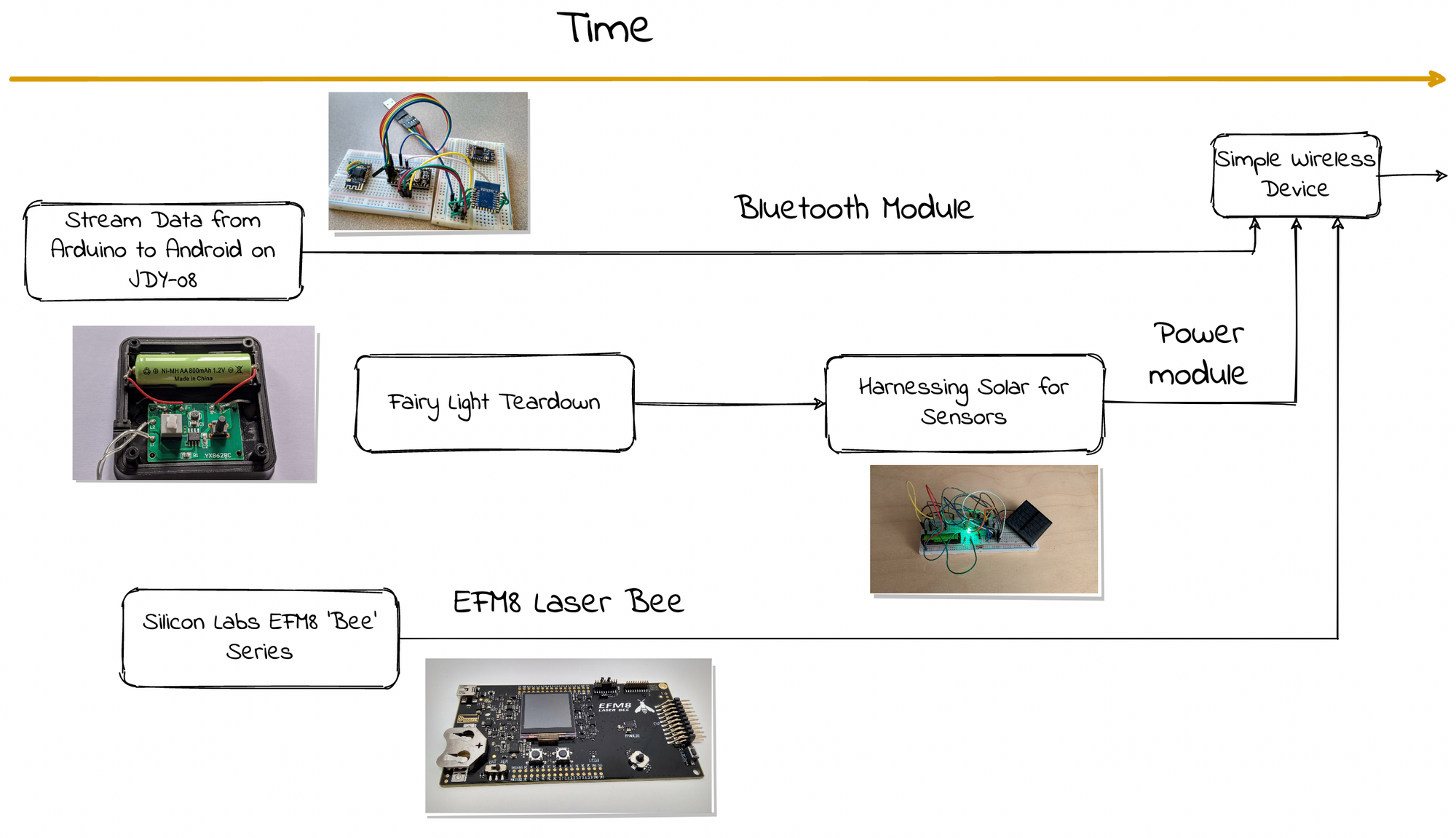
I think I really see the value in building small projects because the ideas tested, the lessons learned, and the things built... these things all come in handy as the projects scale up in complexity.
Background
It is disruptive for me when I have to stand up, pick up my multimeter, and probe a wireless or remote circuit because it breaks my train of thought and disrupts my workflow.
So I embarked on a search of wireless multimeters, and they cost around \$40 to \$60 each. That is not terribly expensive, and in a pinch I can use them, but these are big bulky things, and I don't like having them because they are hard top position and mount. Furthermore, they will add more clutter to my table, which has limited real-estate.
My requirements are quite simple: a voltage measurement range of 0 ~ 3.3V and current measurements within the 0 ~ 50mA range are sufficient for what I do. This is the small-time league for multimeters. I don't need resistance measurements, continuity, or capacitance because I'm more interested in the time-series measurement of the circuit's performance.
The final goal is to have a circuit that does these measurements and broadcast it over Bluetooth for a listening device to capture. This will help to automate the testing process and go a long way to profiling battery powered devices.
Prototyping
Before jumping into anything, it always pays to do a reality check of the project in my head versus the project in the real world. Is it useable? Can it be done?
I wired up a Bluetooth module (JDY-08) that I had lying around with a Arduino, and quickly wrote up some code that would allow the Arduino to take analog data, push them to the Bluetooth module, and then publish it over the bluetooth link.
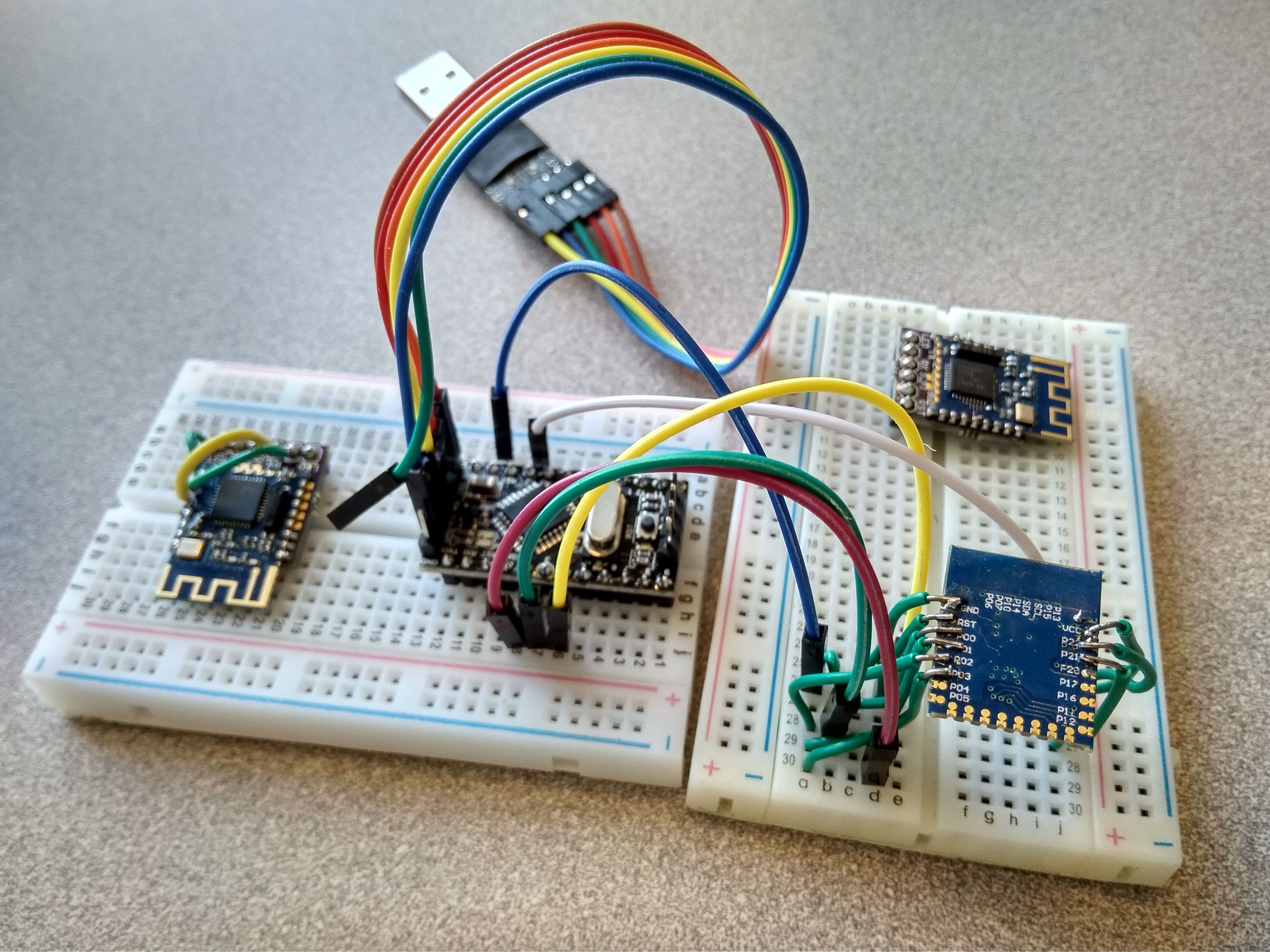
I basically followed the instructions I wrote for myself in the post above 👆. In my case it was easier because I was using the Seeeduino v3.2 instead of the Arduino UNO. The Seeeduino works at 3.3V instead of 5V like the Arduino, and this voltage level is required to work with the Bluetooth Module.
Additionally, I didn't need a USB-UART module on the Seeduino versus the Arduino Pro Mini.
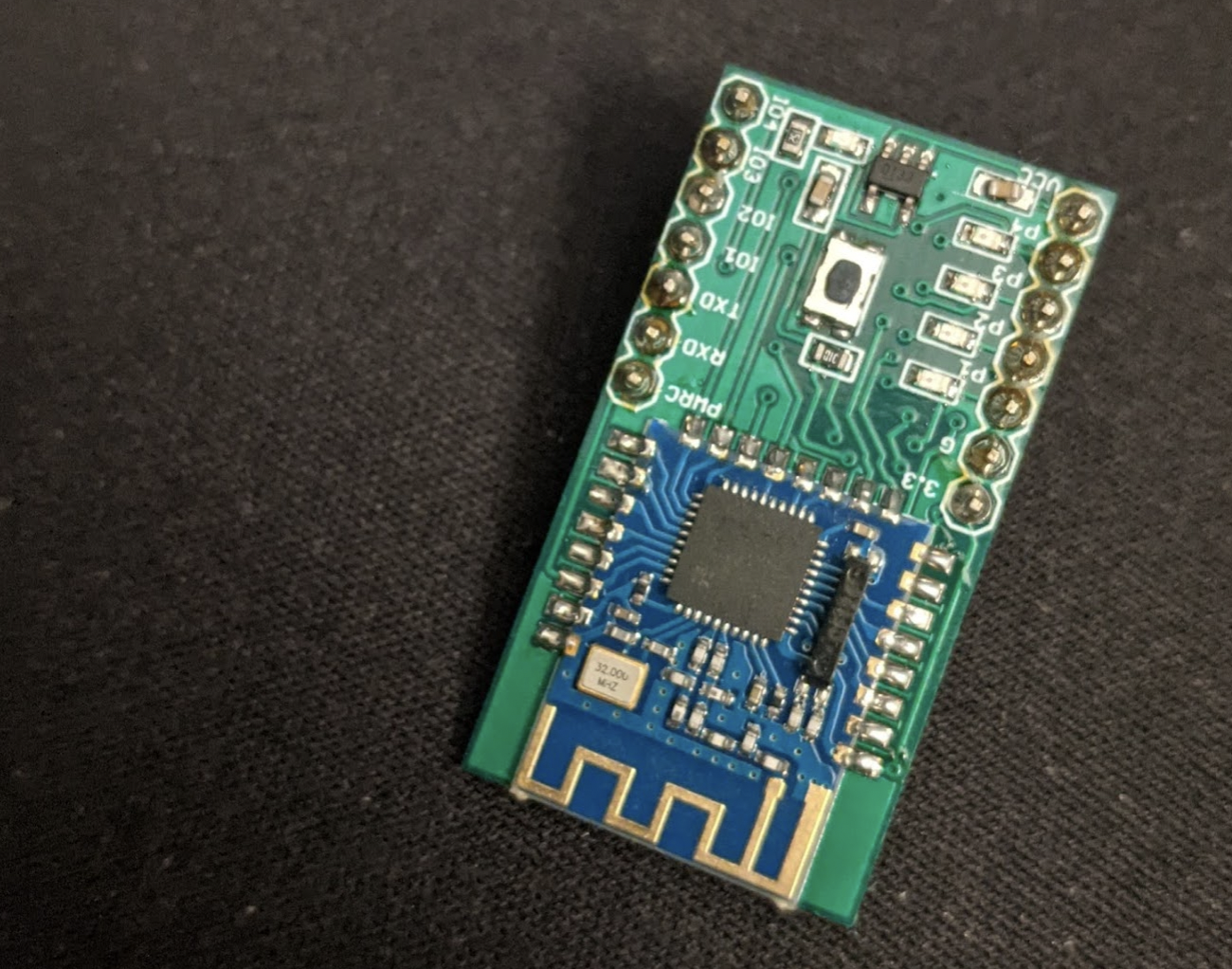
Since the last time I worked used the module, I also created a breakout board that allows me to quickly prototype the circuit instead of having to solder individual wires to the module.
I wired up a simple voltage divider circuit on the breadboard and wrote up a small script for the Arduino to send the data to the BLE module
I was able to read the data broadcasted by the module from the nRF Connect App and the output corresponded to what I was measuring with my trusty multimeter. Great! Time to move to the next step.
Selecting a current IC
I soldered the current measurement IC (MAX9938) to a breakout board from ARIES (which was way too expensive at $10 for a simple board!), and verified the accuracy of the measurement.
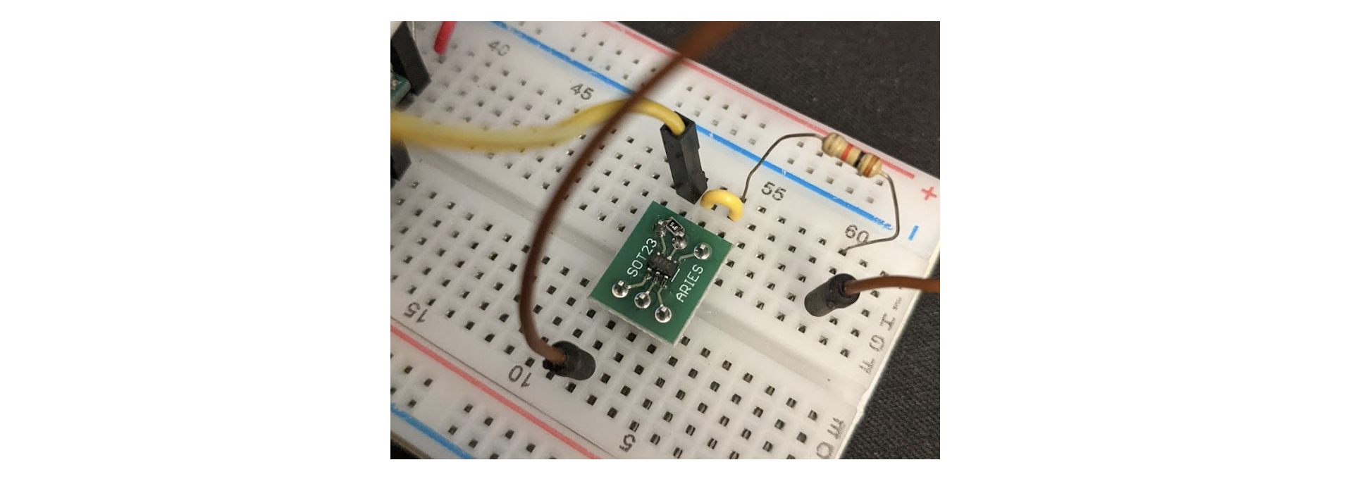
The difference between the measured current and the actual current is 1%, which is not fantastic, but remembering that this error is approximately 10uA, it is well within the noise of the circuits I would be measuring.
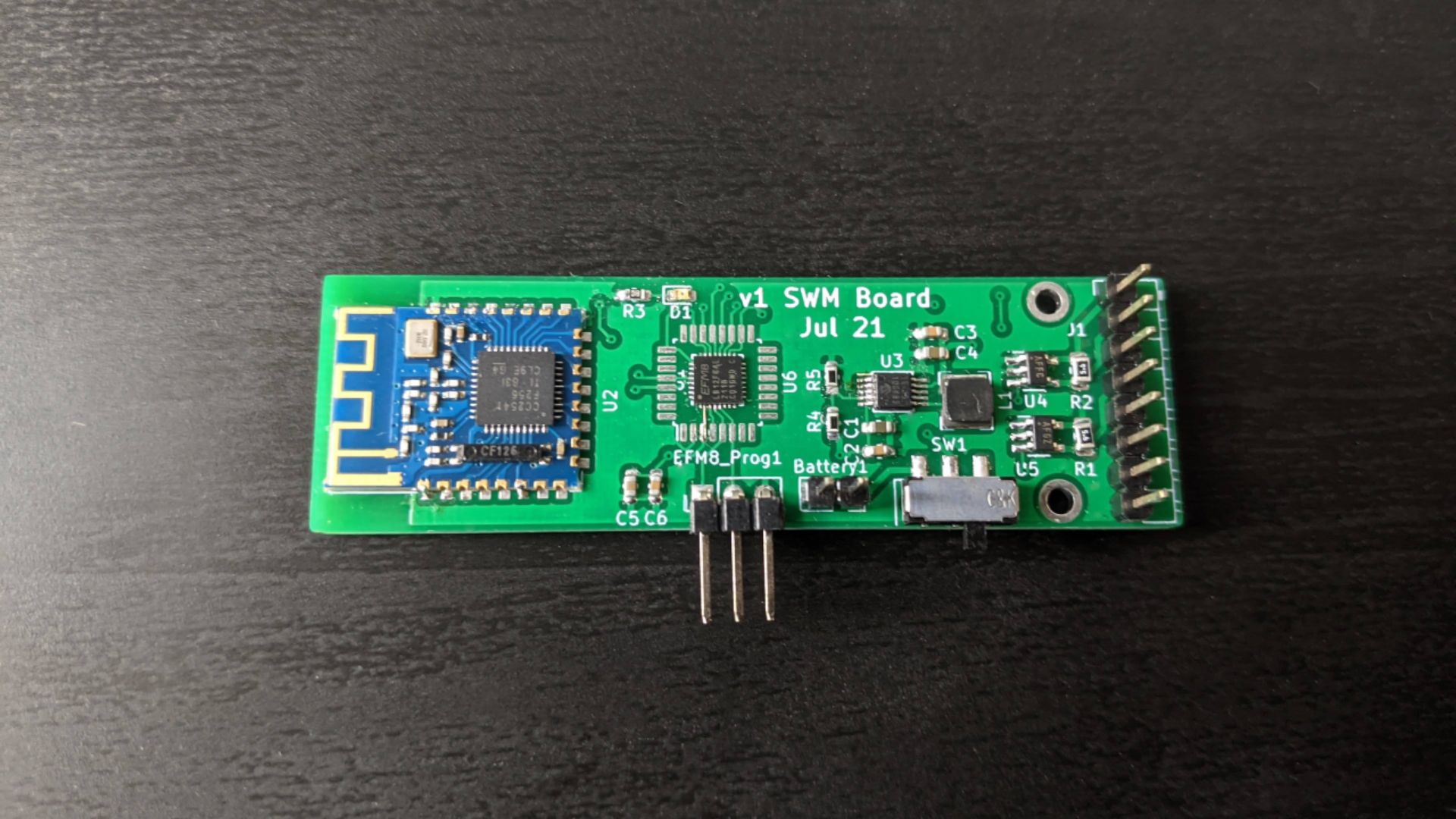
First iteration
I designed the circuit board in KiCad.
I chose to use the EFM8 Laser Bee from Silabs because I had quite a good experience building with it the last time and the EFM8 Laser Bee is tailor-made for interacting with analog circuits.
Unfortunately, while I had a good experience with Linux and Windows previously, I didn't have a good time in Mac!
- Silabs 8-bit compilation backend uses Keil's C51 compiler which is stubbornly stuck in the 32-bit era with no plans to upgrade - Apple does not provide any sort of backward compatibility for 32-bit programs.
- I switched to Windows, but then I ran into issues with getting the STK to program external devices where it would simply report an error. I eventually found that a 1k pullup is absolutely necessary on the clock line (C2CK) and this was very sensitive. I eventually switched to a J-Link, and the programming was much more stable.
Board errors
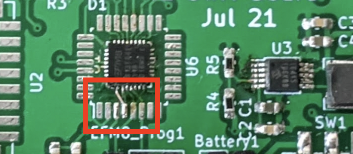
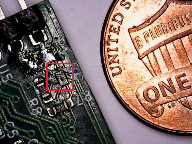
After solving my woes with programming the device, I realized that I made the simple mistake of not powering the VIO line. 🤦 Here is the rectification I made with a tiny bodge wire, made from stripping down another wire. It connects the pin directly to an exposed 3.3V pad. This pad is about 0.4mm wide, so it is a really delicate operation.
To power the circuit, I used the Ultra-Low Boost Converter that I made when exploring the solar fairy lights. This allows this circuit to be powered from voltages anywhere from 0.8V to 5.25V. This is an important voltage range. 0.8V is the lower end for a rechargable battery and 5V is the voltage from a USB port. This means that this device can be powered from a wide range of power inputs, which adds to its versatility.
The first version worked well enough for me to test out my ideas further. I verified that the boost circuit was working, and I could program the EFM8 microcontroller successfully and have it talk to the Bluetooth module.
I used a cheap breadboard to wire up the circuit and because some of the rows did not connect the pins that they were supposed to connect, it took me awhile to figure it out my problems came from the breadboard and not the soldering job that I did.
Designing a mobile app
I didn't want to use the nRF Connect App forever as it isn't easy to interpret the data that is being sent as it only publishes the raw values the Bluetooth module. Therefore, I decided to create my own app.
Flutter is a framework that allows you to build both iOS and Android apps using the same codebase, saving teams that build serious apps the trouble of maintaining two separate branches of expertise.
The main benefit for me is that it is really popular, and with hundreds of tutorials sprawled out across the web today, it is easy to find someone who has the same question or doing the same things that I am doing.
Version 1
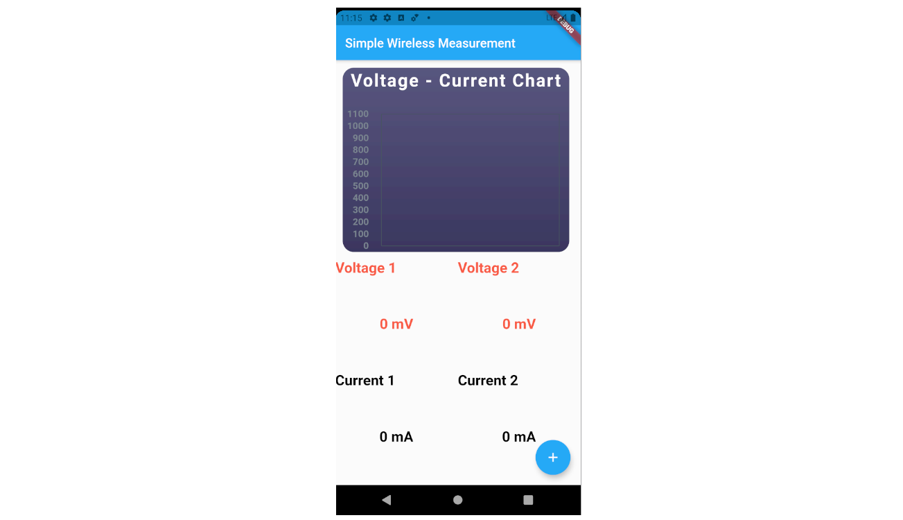
The first iteration was hilariously ugly - it put all of the measurements onto the same page and the same graph. It also searched for one hardcoded device, matching the MAC address on the device before it started to read the data. Obviously this is not very extensible because the source code has to be changed for each new device.
Version 2
The next version added a screen that you could use to search for surrounding Bluetooth devices as well as a dedicated screen when a device is selected to display the data in a nice big font. It is much more usable.
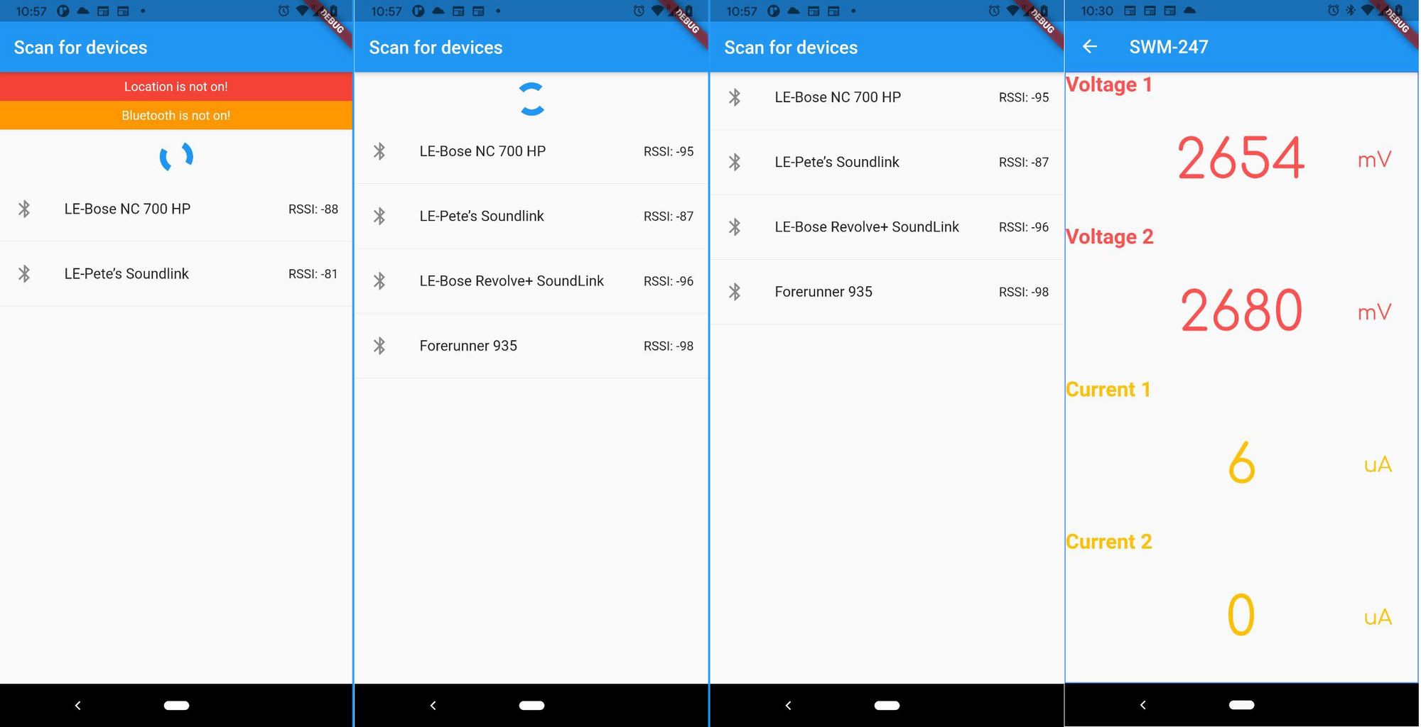
It also checks if Bluetooth and Location and warns the user if it is not enabled. Interesting tidbit: Location is required for Bluetooth operations because your location can potentially be picked up with Bluetooth, and enabling Location is an acknowledgement on the part of the user that they are exposing their location data, even though the GPS might not be used. I find this to be a rather bizzare and energy-sapping way of getting acknowledgement from the user just to use Bluetooth.
Version 3
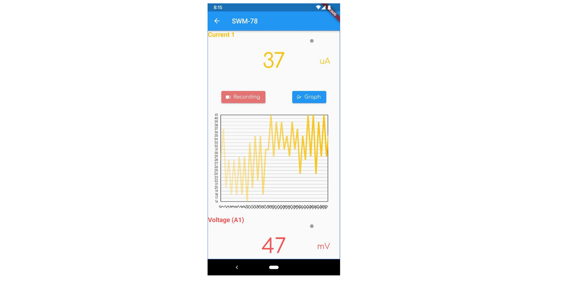
The next version adds some more features such as the ability to see a time-series graph as well as record the data.
Going Mini
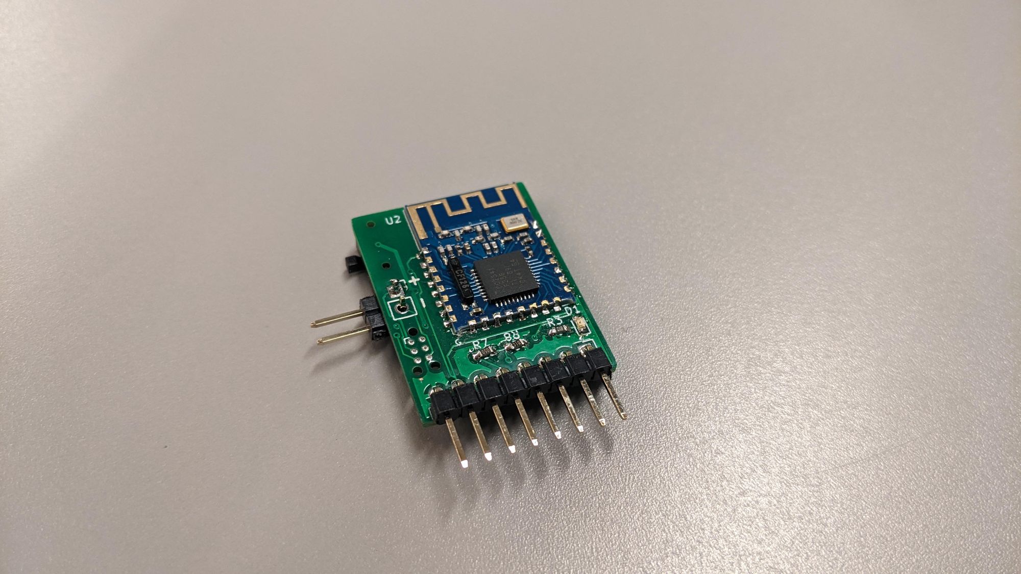
The board also underwent miniaturization once I figured out and fixed some of the bugs in the original design. The mini version of the board features components on both sides, and a Tag-Connect programming header. This is significantly smaller than the original design (40%!), but is still comfortable to work with.
Switching out the current measurement
This board is half the size of the original board, and changes the current sensing IC to the MAX44284, the reason being that the original current measurement IC had a minimum voltage input of 1.6V because it uses the line under measurement to power itself. This is great for reducing part count and traces, but non-ideal for me as I need to measure very low currents.
The MAX44284 has a voltage range of -0.1V to 36V, and it is powered by 3.3V which made the routing slightly more complicated. However, because it is uni-directional, I found this to be a limitation when measuring battery circuits where the current would flip depending on when the battery is charging or discharging.
Finally, I switched to the MAX40204, which allows bidirectional current sensing at the cost of losing some precision as its range is split between the positive and negative measurements. It also features a more complicated circuit. Another catch was that it is currently not available in a TDFN package, so I had to tackle the more challenging WLSCP package, which is like a BGA package in the sense that it doesn't have exposed pads, so soldering is mostly a guess and check affair.
But after some tries, I learned how to solder WLSCP ICs:
- Clean the pads with some isopropyl alcohol
- Add a dab of flux and then apply hot air with some tweezer nudging to keep the IC in place.
I didn't have the tools to reball the IC, but everything worked as expected because the IC already had balls of solder.
With the tight placement of the board, I also had to switch to a 4 layer board, and generated instructions for PCB assembly. I used JLCPCB, and their turnaround times are quick, but they have a restriction that may put quite a few people off: they don't offer their PCB assembly service for parts sourced elsewhere. It has to be part of the parts category list that they provide, which is honestly one of the most annoying parts of the process because the search is slow and clunky. However, JLCPCB was able to provide most of the jellybean parts like resistors and capacitors, and it cut down my soldering time in half. I'm surprised to find out how much time I spend sorting and soldering capacitors.
Switching out the bluetooth module
I had to switch out the JDY-08 module that I was using because it got really expensive and hard to find. Today, it is approximately \$3 ~ \$4 per unit vs \$1 ~ \$2 when I bought it. Luckily, there are other JDY modules that have the same pinout. They also have improvements that make them more usable.
I selected the JDY-23 as the alternative module. It costs approximately \$1 per module, and has the benefit of having the same pinout. It also has a lower current draw (< 50uA vs 9mA), and a default baud rate of 9600, which is the standard baud rate for SoftwareSerial and Arduino. This will make it easier for the Arduino build of the device.
Conclusion
The Mini version works well for testing and prototyping because it is compact. I also have plans for a Nano version, which will be about the size of a nRF24L01+ module.
I learned a few new things with this project, such as how much time savings I can get even if I have just the jellybean parts soldered, and how to solder a WLSCP package.
I am currently happy with where this project is at. But I don't consider it to be in a finished state, because there are always improvements to be made. I expect to post a few posts detailing improvements to this device in the future. Expect to see this device being featured heavily in other projects too, as it will be my main tool for measuring power draw in the field for other IoT devices
If you liked this post, please consider subscribing! I always love to connect with my readers and find out what they think.