M.O.O.S.E
Design Competition 2019! This year features some cool new sensors!


Introduction
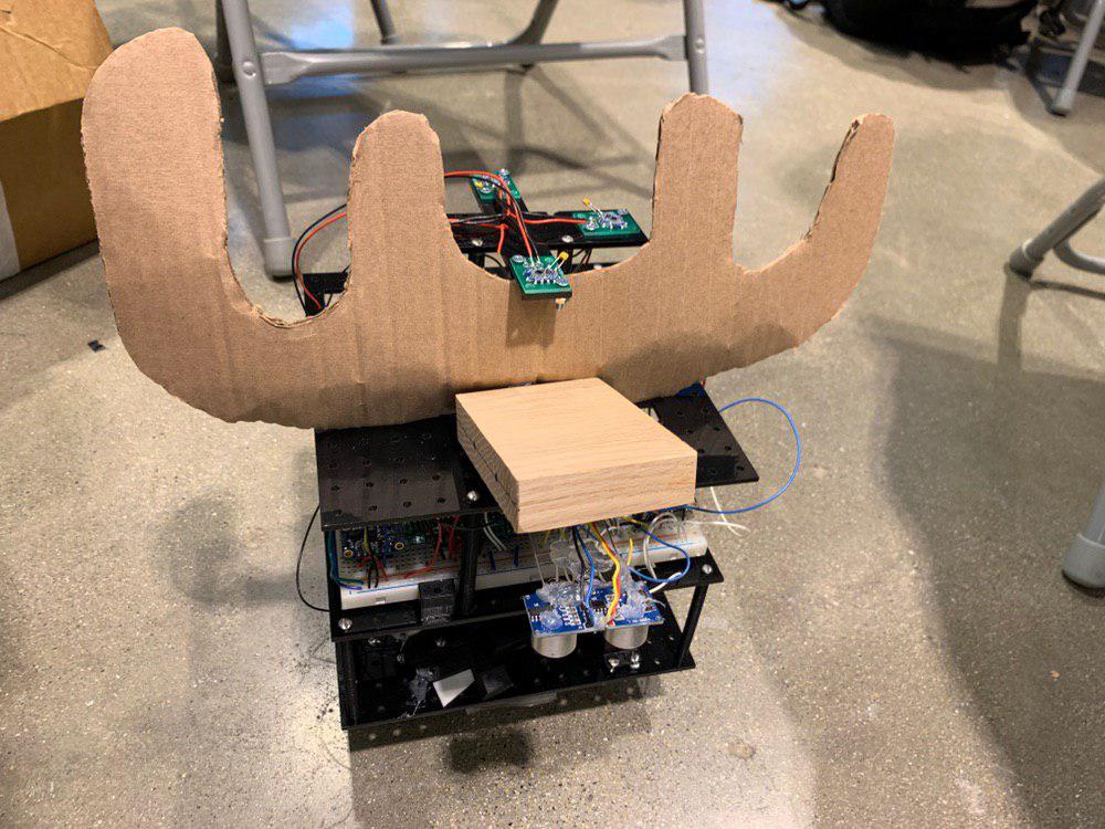
The Moose is a robot for Design Competition 2019. It is designed for configurability in mind. The base design starts with the layout of the battery and the motors to determine the land pattern of the robot. The base board uses a grid of 0.5 by 0.5 in holes designed for 4-40 screws on a piece of acrylic 7in by 7in. By using a grid pattern, it allows the components to be moved and secured in place.
Each layer can be added by using standoffs, and this provides additional room to mount additional components. The bottom of the first layer includes the grabbing mechanism and the block finder module. The top of the first layer includes the motors, wheels, and battery, as well as the servo for the block finder. On the second layer the electronics are breadboarded, and on the top layer the sonar and the vive sensors are mounted.
Electronics
The robot uses an ESP32 Feather over bluetooth serial to connect to a computer. An Adafruit Seesaw was used for controlling the direction and the PWM values sent to the MAX1480 DC motor driver from Pololu. The motor driver controls 12V N20 motors from Pololu, which are used for the wheels and the rack and pinion system.
Power is supplied by a BOSCH 12V drill battery. The 12V was supplied to the motors, and a 5V regulator was used to supply power to the USB pin on the ESP32, which distributes 3.3V to the rest of the system.
The rangefinder was a VL53L1X Time-of-Flight Distance sensor carrier from Pololu. A BNO055 orientation sensor was used for absolute angles, and vive sensors were used for location sensing. A Teensy 3.2 was used for obtaining vive sensor data from the 4 vive sensors on the top of the robot and it communicated with the ESP32 over UART. The retroreflective sensor was made with a phototransistor and a laser controlled from a on on the ESP32.
The information is set over Bluetooth Classic to a computer over a serial port as a string delimited by spaces. Single letter commands sent from the computer are used to control the robot.
Block finding

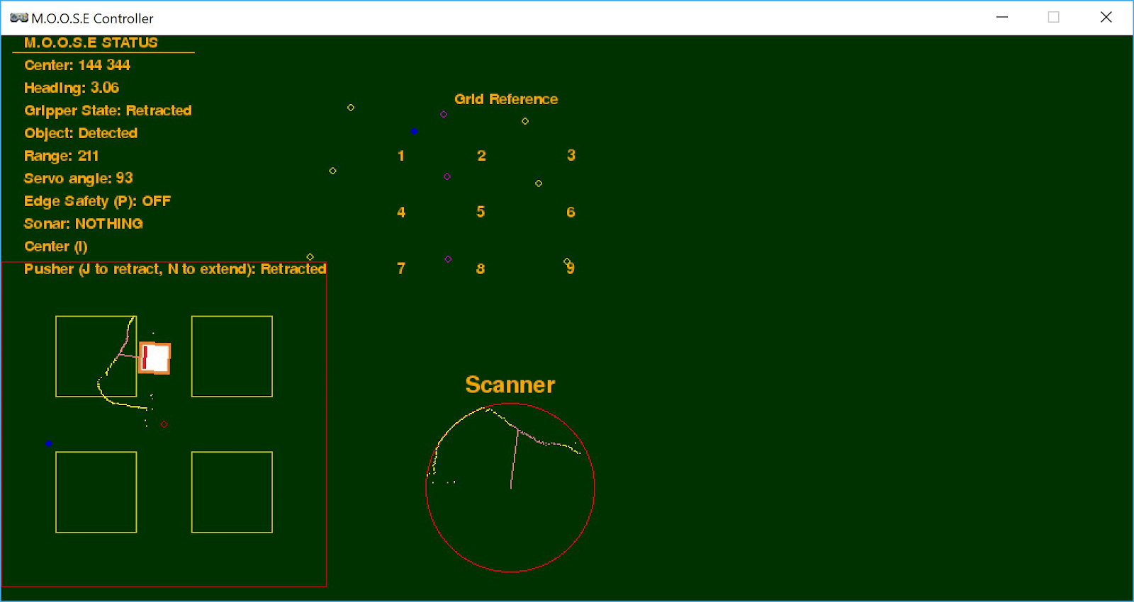
A servo is mounted on the base of the robot and scans from 0 to 150 degrees. On the servo, a rangefinder from Pololu is mounted close to a retro-reflective detector. The data that is streamed back to the GUI is the current angle of the sensor, the range, and if a retroreflective object is detected. This is then stored as a dictionary in Pygame Zero and this allows the values to be updated as the robot scans each time. It is plotted as a circle, and yellow represents the range, while pink represents a retroreflective point. The scanned points also take into account the orientation of the robot, allowing the scanned points to be placed in an absolute manner on the GUI, instead of just being relative to the orientation of the robot.
Grabbing Mechanism
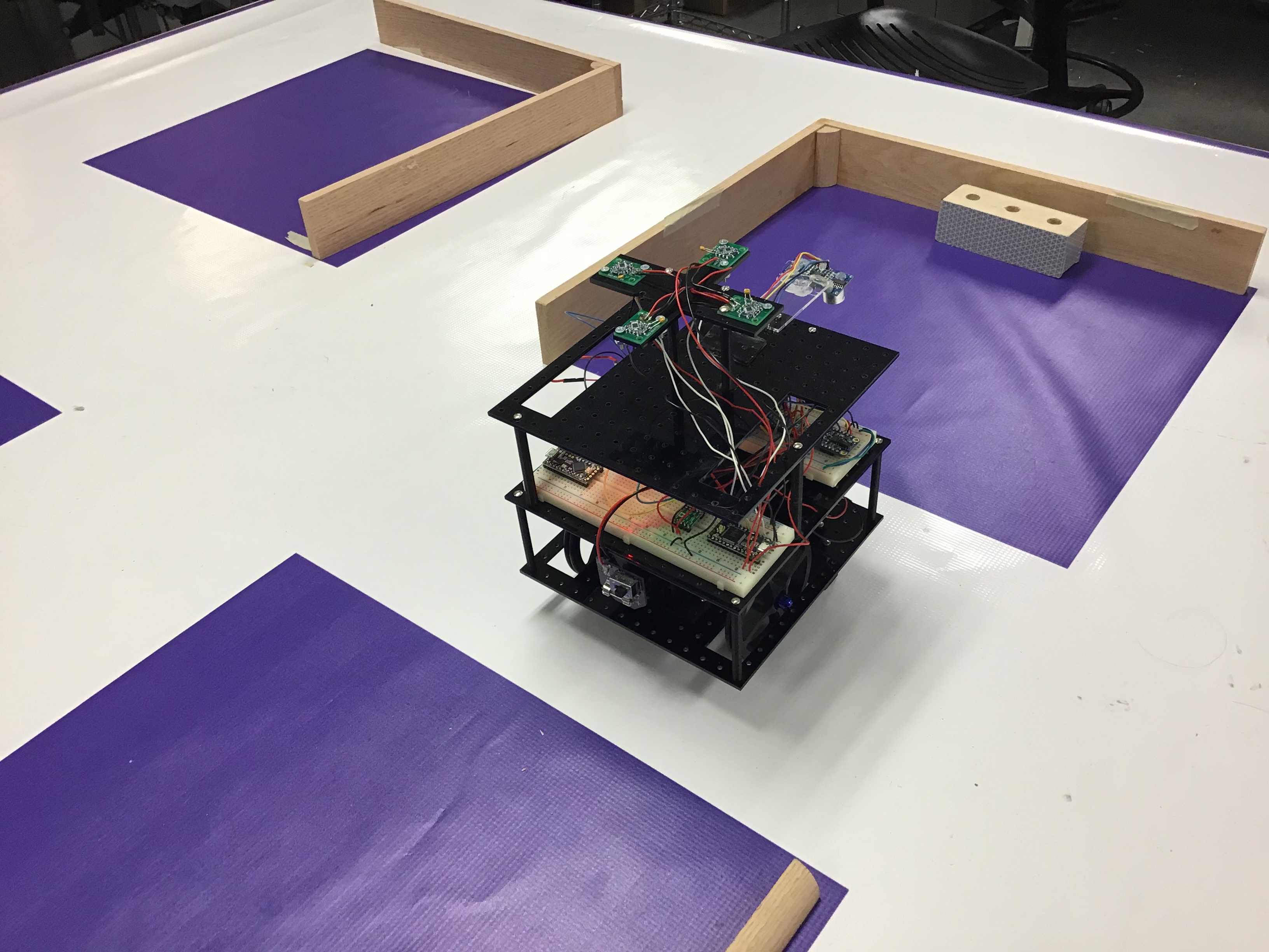
The robot uses a rack and pinion to extend a block that has a piece of tape on the front. By extending the rack, the robot can grab a block, and by retracting the rack, the robot can release the block.
Graphical Display
The information is parsed and displayed in Pygame Zero.
The top left displays the robot’s current status. Below is a graphical layout of what the playing field looks like and the robot’s position within it. Also included is the approximate location of the robot as indicated by the vive sensor as a blue dot. The scanner’s information is also integrated onto this map.
On the top right is a grid reference of the calibration points that map to each vertex of the playing field. This maps directly onto the representation on the bottom left. Point 7 is used as the reference point, and all other points are displayed relative to that point given some scaling factor. Here it can be seen that the vive’s representation of the playing field is distorted in a non-linear fashion, therefore, navigation by purely relying on the vive sensor is not reliable. In the grid reference, the robot’s position is also represented as a blue dot. Whenever it reaches one of these calibration points, the number can be pressed on the keyboard and it snaps the location of the robot to the correct vertex. On the bottom right is the scanner. The limit of the scanner is represented by the red circle, and the scanned data is represented by yellow and pink dots, where pink dots are points where the retroreflective sensor returns a positive value.
A list of available commands are:
- Up, Down, Left, Right: Move the robot in the specified direction
- Space: Stop the robot
- J: Extend the knocker, N: Retract the knocker
- E: Extend the sticky gripper, Q: Retract the sticky gripper
- K: Lock/Unlock scanner from 90 degree position
- P: Edge safety on (stops the robot when the sonar detects a distance greater than expected)
Localization
Moose utilizes both dead reckoning and vive location sensing to determine its location. While the vive is accurate, it is noisy to 0.1 in, and the projection of the vive location does not match the plane of the playing field. An attempt was made to use a linear and a quadratic fit, but both these methods failed to produce any usable data.
Therefore, in order to navigate, Moose uses dead reckoning to determine its location from its previous location. The dead reckoning is based on time which Moose is moving forwards or backwards. Orientation is based on the BNO055 sensor which is very reliable, therefore errors from dead reckoning only come from slipping or jerking of the robot. Errors also come when the robot moves in a skewed direction because the motors are not at the same speed. Over time, Moose’s actual location will deviate from the position displayed on the GUI.
In order to fix this, calibration points are set up at each junction of the playing field and they are represented as dots in a grid in the GUI. Moose’s position is represented as a blue dot on the GUI. This method of representation allows the relative direction of each point to Moose to be determined approximately. When Moose reaches a calibration point, the number which represents the calibration point can be pressed, and it will cause the x and y coordinates of Moose on the GUI to be set to that point. Although the projection of the vive sensor is not accurate, it is quite consistent, so we know that Moose is at the calibration point, even when the dead reckoning data appears otherwise.
This overcomes difficulties in using the vive sensor and dead reckoning for movement by leveraging the relative advantages that each offers, the former having consistent readings, and the latter providing good short range location sensing. This combined allows for a fairly reliable method of navigating blind.
Mistakes
The battery was not locked down, causing the robot to shake when it started and stopped because it was the heaviest part of the robot.
The extender should have been programmed to extend further out. This would have prevented the robot from going too close to the edge
A weight should not have been added to the front of the robot. This caused it to tip forwards.