Conversion Mod: Wired to Bluetooth Headphones
I upgraded my Custom One Pro headphones with Bluetooth and touchpad controls so I don't get violently yanked back to my table every time I forget my headphones are plugged in.

How I upgraded my headphones to be fully wireless with a $2 board
How it began
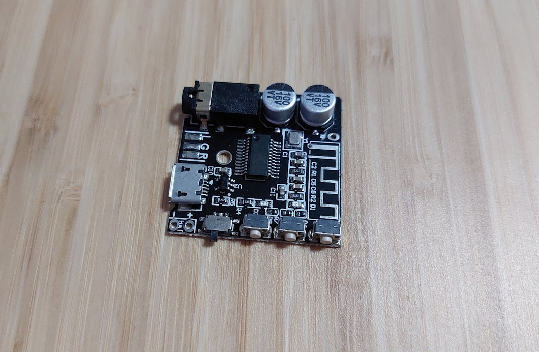
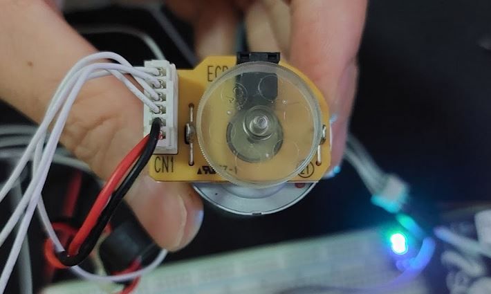
While browsing AliExpress, I came across this rather impressive little board:
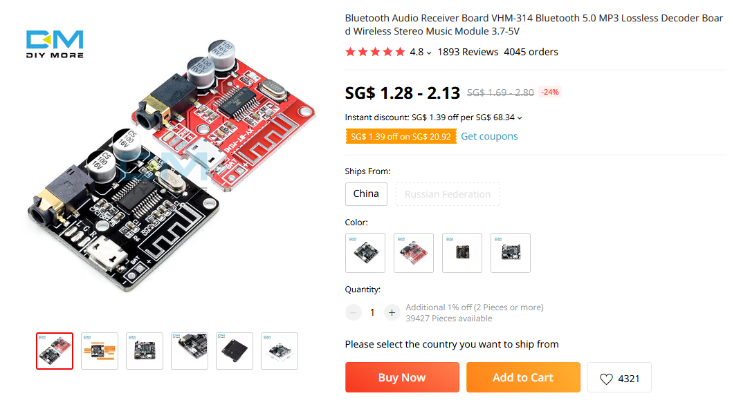
A BLE audio board is not crazy by itself; there are a ton of Bluetooth speakers out there. The impressive thing about it is that it is $2. Wireless is hard. Audio is hard. Therefore wireless audio shouldn't be cheap and sit on a tiny 30mm x 30mm board, but here we are.
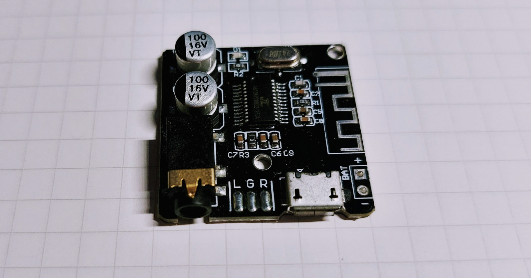
If you have read about some of my other projects, then you would know that I delight in finding ultra-cheap microcontrollers and boards and this board is no exception.
For just $2 you can easily upgrade old speakers into wireless ones just by plugging this board into the audio jack, nothing else needed. It helps to cut down on the number of wires snaking across your desk and gives your existing speakers a new lease of life. What's not to like?
Initial testing
I tested turning my wired headphones into wireless ones by plugging it into the board and attaching a powerbank to the USB input to test the feasibility of wireless headphones. I've never owned any, so I wasn't sure if I would like it or not. It doesn't make sense to commit hours to a project that I don't even like the idea of.
My impressions were quite positive. Even though it was very clunky and had wires everywhere, it prevented me from getting snagged multiple times when I was moving around my work area. It doesn't hurt that the audio quality from this Bluetooth board is not bad as well, although the range of the BLE radio on this board leaves more to be desired.
I could have stopped here and have a pretty functional kit with a little 3D printed waist clip, rubber band strapping the entire contraption together and voila, my very own wireless Beyerdynamic headphones in a little retro case. Done. Badabing badaboom.
But we can go bigger
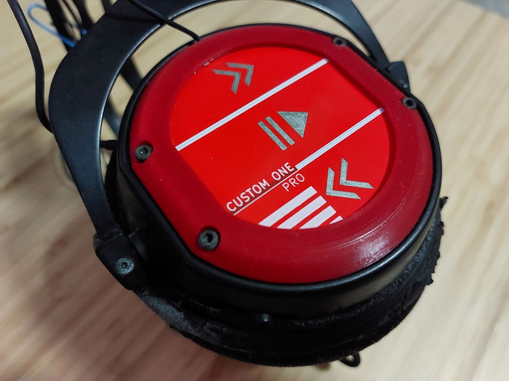
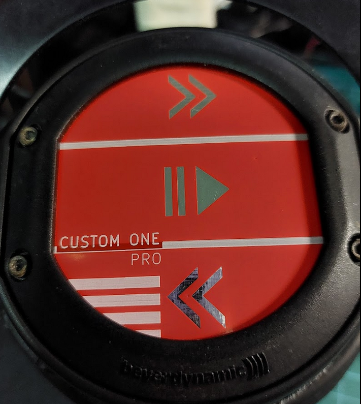
My headphones are Beyerdynamic Custom One Pros. Apart from being discontinued, the other notable feature is that it has aluminium plates that you can replace with other custom aluminium plates with alternative designs.

I thought this feature was a little gimmicky, but I realized that it is a ripe opportunity for adding all sorts of zany new stuff to the headphones because there are mounting holes.
After completing the initial test, I designed a small test mount so the board and a battery would fit where the aluminium plate would go. I also added a short 3.5mm audio jack so that I wouldn't have to modify anything internal to my expensive headphones. The idea is that this
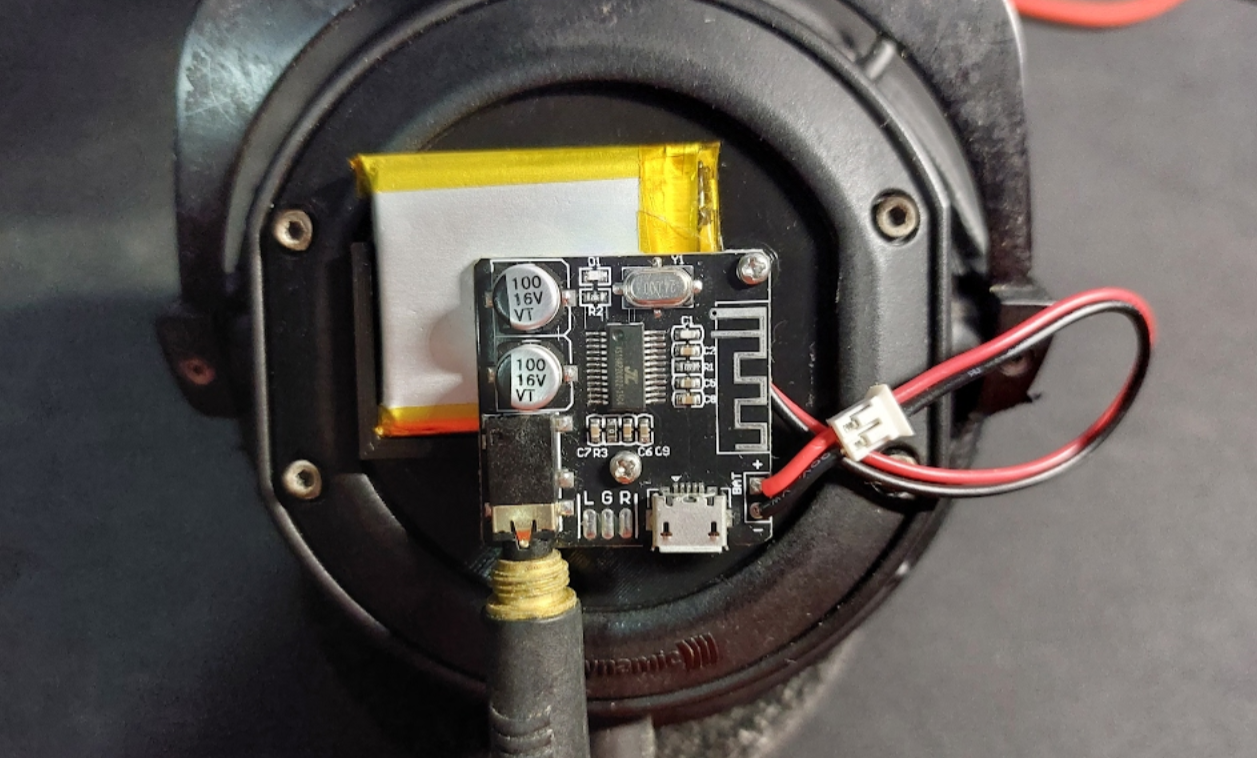
I tested this for a few days, and I liked how comfortable it was. One drawback is that I found myself returning back to my desk far more often than I liked to change the volume or to skip songs. Therefore, I needed some sort of control functionality on the headphones themselves.
Luckily, someone designed an iteration on this board that has small SMD buttons that allows the music to be controlled. If I removed the buttons or otherwise injected my own signals, I could add in my own controls to the board and have a fully wireless design.
The normally open buttons work by connecting the pins on the microcontroller to the ground. In order to control this programmatically from another IC, the output pin on the IC needs to be in an high impedance mode so as not to affect the circuit, and output low when it wants to trigger the desired control.
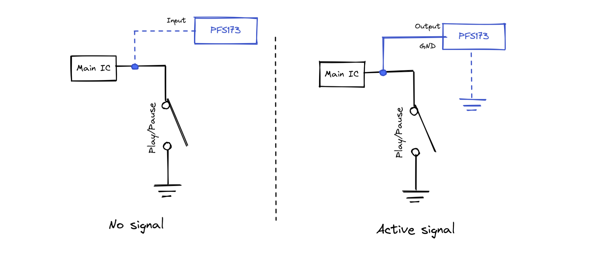
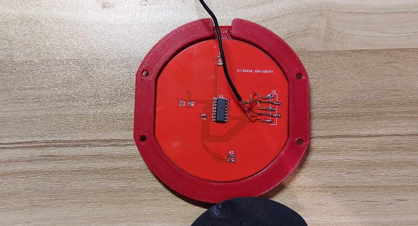
So I designed and built a capacitive touch PCB based on the PFS173 that allows me to control the playback on the main audio board.
DIY Touch Controls with simple capacitive sensing
I don't like the sensation of pressing headphones into my ears when I'm trying to change the music, and the small buttons on the BLE/audio board makes it hard to press accurately.
Capacitive sensing is my answer. It increases the touched surface area and doesn't require force to activate. Capacitive sensing can be easily achieved with a microcontroller's digital pin and a timer.
How capacitive sensing works
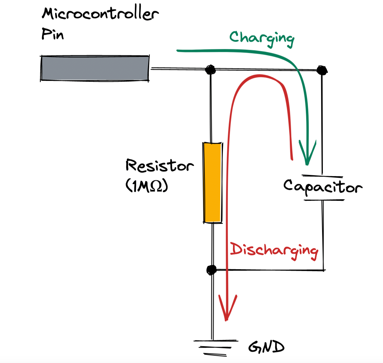
- The capacitor of the RC circuit is first charged by the microcontroller pin going high. The capacitor will be fully charged at this point.
- The microcontroller pin is then changed to a high-impedence input, and the capacitor discharges through the resistor. The amount of charge on the capacitor and the size of the resistor determines the time required for the capacitor to discharge completely.
- The microcontroller pin detects the change in the charge state and notes the difference in time. This is the baseline when there is no finger.
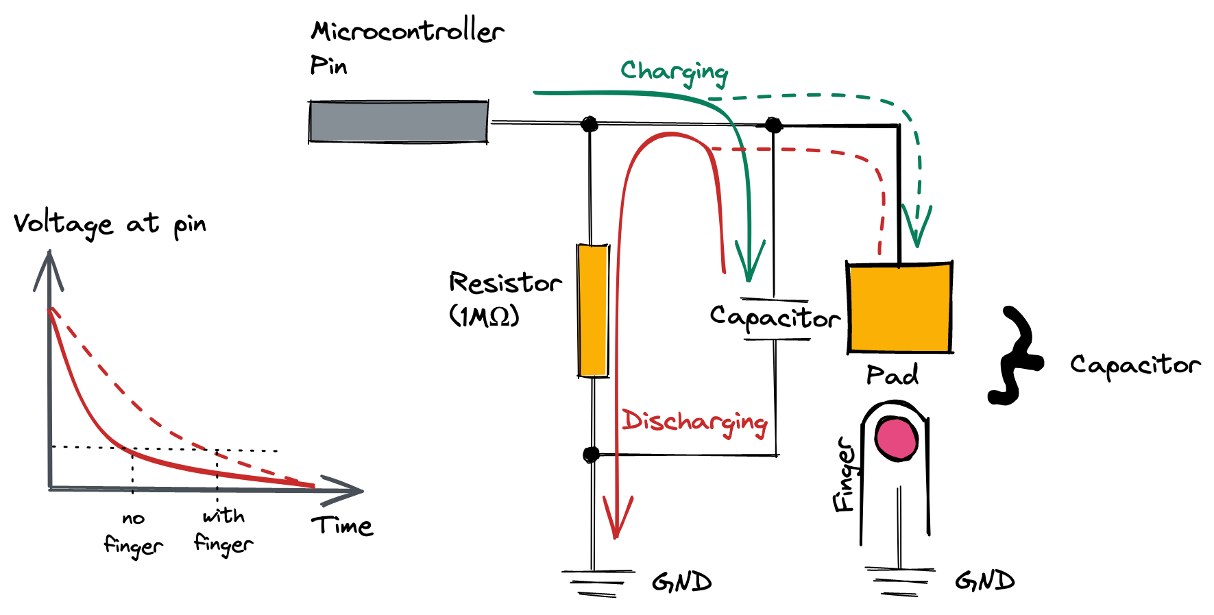
- When there is a finger touching the pad, it acts as a secondary capacitor in parallel as the skin is a good dielectric material. Now there are two capacitors being charged.
- More capacitors in parallel means more charge, and therefore a longer discharge period. By measuring the time taken for the voltage to drop, the microcontroller can tell if a finger is present or not.
Admittedly, this is a rather crude form of touch sensing and it seems quite wasteful when it comes to battery powered circuits as you are essentially charging and discharging the capacitor. The sensitivity is also dependent on the poll rate of the micro controller because of the short time-frame between charge and discharge; too slow, and you miss touches, too fast and you waste power.
A more sophisticated implementation would be to use chips with dedicated touch sensing, like the EFM8 Sleepy Bee from Silicon Labs, or a dedicated touch-sensing chip with a primary microcontroller to get data from the chip. But this method described is simple to implement, and doesn't require any dedicated hardware, allowing me to use the ultra-cheap microcontroller that I have covered a few times, the Padauk PFS173.
PCB design
The Padauk PFS173 is mounted on the bottom of the PCB to keep the touch surface free of obstructions. I initially included an RC circuit, but I found that the internal capacitance of the pins on the PFS173 is significant enough that I did not need an external capacitor. The pins were connected to ground through a 1M resistor.
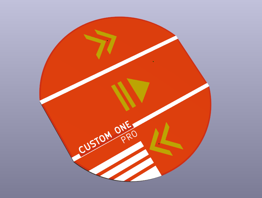
I designed the circuit in KiCad 6, and manufactured it with JLCPCB. I really appreciate that you can now import DXF drawings into KiCad, which allows the shape of the PCB to be designed in a software that is more capable of drawing lines than KiCad.
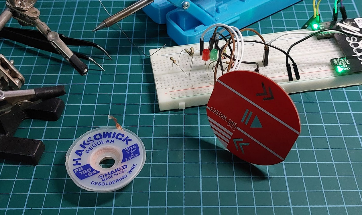
Board Day
I did a small test fit and I might be biased, but I must say that it looks absolutely gorgeous. Gold pads would have really made this pop, but silver is also quite pretty too.
However rare is the project that works the first time around.
When my boards came in, I spent a little over three hours trying to figure out why the output wasn't what I expected. Was it the capacitance? Is the copper plane properly connected? One of the buttons wasn't working
I discovered later that a particular pin PA5 requires a pull-up resistor for it to act as an output, listed in the errata of the datasheet. Once I added a 10k resistor and double checked my soldering, everything worked as it should!
Final Assembly
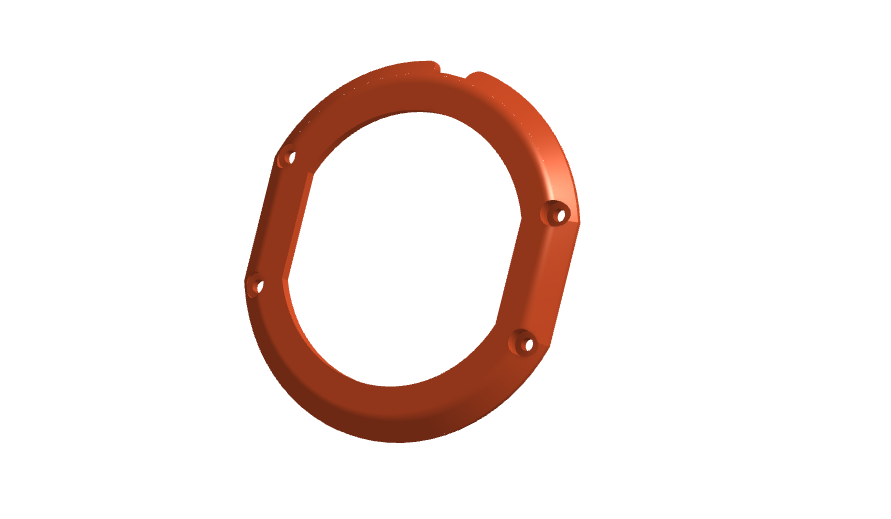
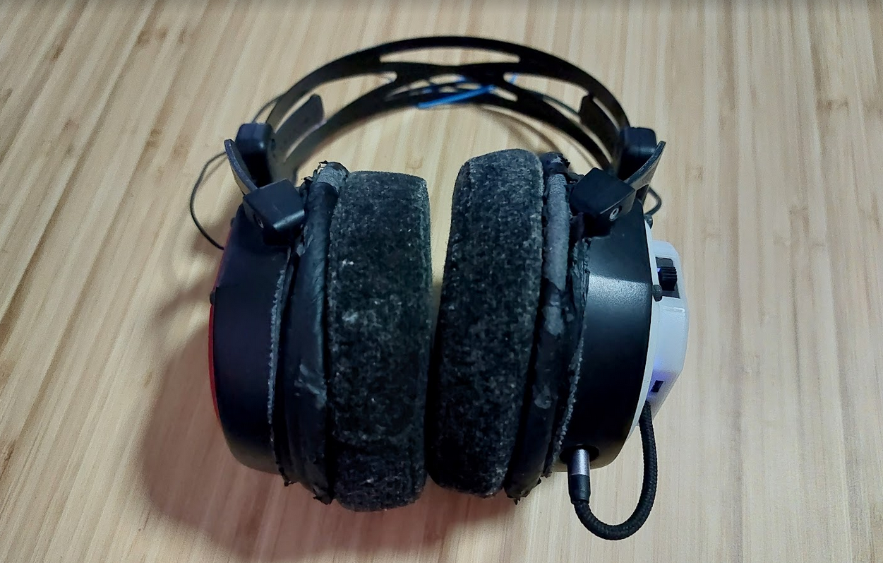
When the boards came in, I attached it to my headphones a customized 3D printed mount. The original mounts were meant for aluminum plates and had no holes to thread a wire through. The new mounts have a notch on the top to thread the wire through and connect it with the BLE board on the other side.
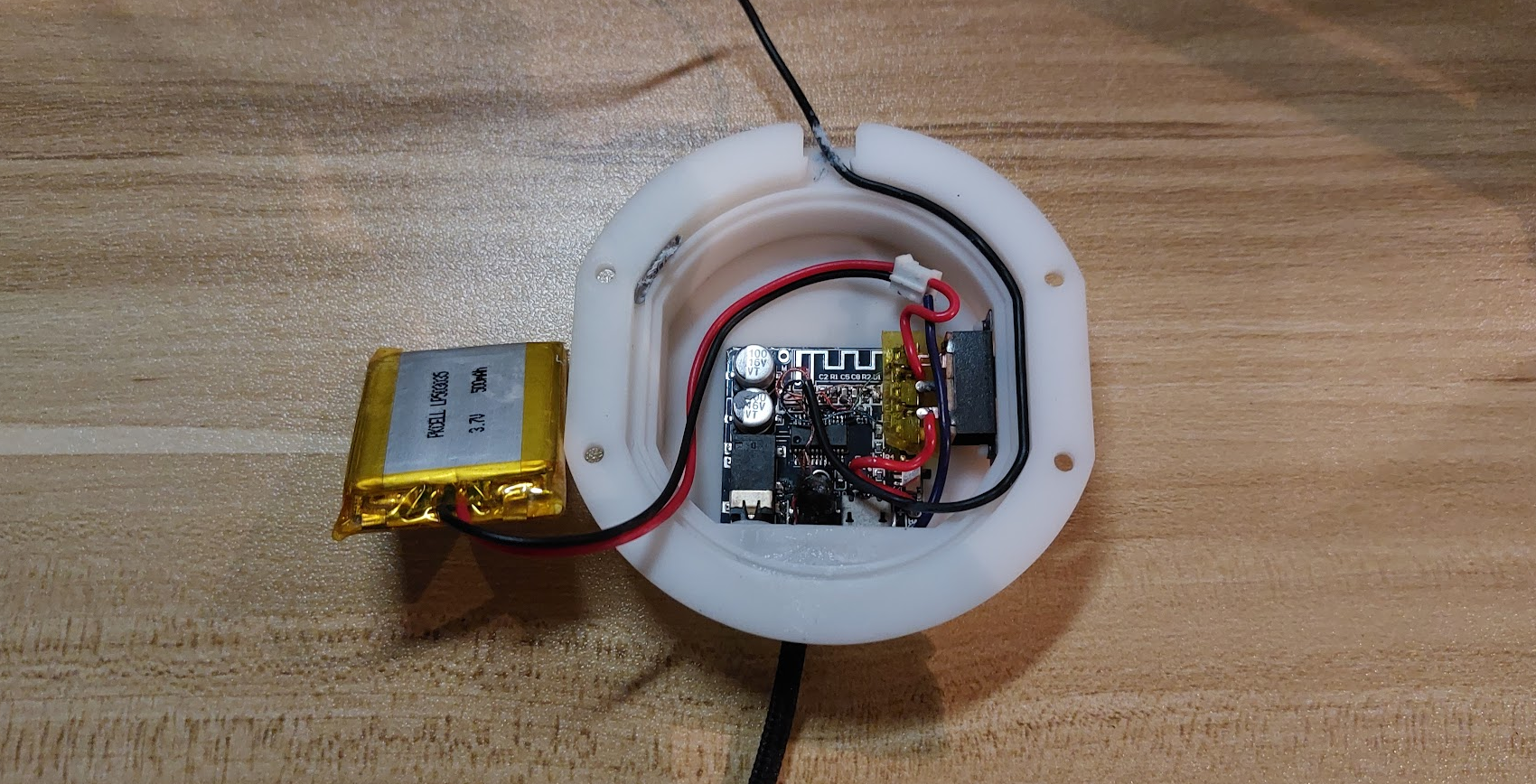
On the other side of my headset, I 3D printed a covered mount for the BLE board and battery and glued everything in place. I added a power switch to cut power directly from the LiPo battery, as well as a 3.5mm cable to the BLE board that would allow me to switch between wireless and wired modes.
The hardest part of this assembly was soldering to the buttons on the BLE board.
I am coming around to using adhesives because they can be very strong when used properly and simplify the overall design. Plus less screws also means a cleaner surface.
Closing thoughts
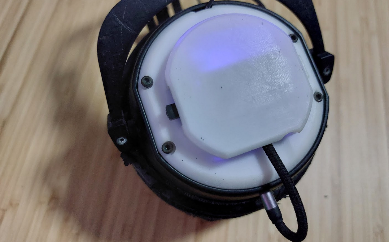
I think it looks fantastic and I love how low profile it is on my headset. The touch controls work perfectly for controlling playback. And if I want to switch back to the wired experience, all I have to do is to unplug the jack from the mod, and plug the original jack in.
I think it is fair to say that it has met the outcome of not only finding a great use of this super cheap Bluetooth module, but has also provided a very useful upgrade to my headphones. Now with no wires to tangle, and a wireless touch control interface, it really is a dream to use.
Until next time! If you liked this post, subscribe and drop me a hello!
Footnotes
Does it do noise cancelling?
No.
Endnote: Why I use Padauk's proprietary toolchain instead of an open source one
I like using Padauk ICs in my personal projects because they feature an extremely limited feature-set which I have to think of creative ways to work around, making development interesting for me. Plus it is easy enough to wrap my head around
I also use Padauk's proprietary toolchain even though an open source one exists - SDCC. The proprietary toolchain works well with Padauk's entire line and allows for effective debugging using the ICE. At this point, SDCC still doesn't support debugging which is an essential feature to me for embedded development.