A WiFi Coprocessor for STM32
Adding WiFi to any project using the WiFiNINA library and the ESP32 as a coprocessor. By replacing all the Arduino-specific functions with generic functions that can map to any HAL, now any chip (NXP, Microchip, ST.. etc) can use the ESP32 as a WiFi coprocessor.

The STM32 is a great device but you know what makes it better? The Internet! However, STM32 chips do not natively come with WiFi capabilities, relying on other modules to prove connectivity options.
Tldr; add zippy WiFi capabilities to any project with any IC. All you need is transmitting and receiving a byte via SPI, and reading + writing to GPIO pins.
 benlhy
ESP32
The great thing about using the ESP32 is that a lot of Internet-words have been written as tutorials, documentation, and guides. So if you've a problem, someone out there has probably ran into it already.
In addition, compared to its WiFi only cousin, the ESP8266, the ESP32 TCP/IP stack properly supports TLS and SSL. There is no need to include a TLS library, reducing the code siez and complexity.
The low cost of modules doesn't hurt either. It currently costs \$4 to get a module that you can just slap onto a PCB. If a breakout board is more your speed, Adafruit provides a WiFiNINA breakout (only \$10!) consisting of just the ESP32 with all the interesting pins broken out and the pins voltage shifted to work with 5V microcontrollers.
The WiFiNINA library is interesting in that it uses SPI to talk to the ESP32 module, rather than the standard AT command set. SPI can go up to 8Mhz on a standard Arduino whereas the baud rate for UART is in the low 100k's. This means a zippier experience when talking to the WiFi module, and potentially easier debugging as well, because SPI signals are easier to measure and decode.
Getting it to work in Arduino
The first step is to run through a demo to make sure that all hardware is working. Since I have a ESP32 Dev Kit on hand, uploading new firmware is as simple as plugging in a USB cable. Otherwise, you might need a USB-UART connector to connect to your ESP32 IC.
I am using Adafruit's fork of the WiFiNINA library, modified to work with the ESP32 module:
adafruit
To flash, install the esptool.py
$ pip3 install esptoolThen put the board into flashing mode and flash, replace COM7 with the port number of the board (check Device Manager -> COM Ports):
$ esptool.py --port COM7 --before no_reset --baud 115200 write_flash 0 NINA_W102-1.6.0.binPlease note that to set the ESP32 module into flashing mode, you will need to hold down both BOOT and EN buttons on the ESP32. When you run esptool.py, release EN first, then BOOT and you should see it start to upload code to the board:
esptool.py v2.8
Serial port COM7
Connecting.......
Detecting chip type... ESP32
Chip is ESP32D0WDQ6 (revision 1)
Features: WiFi, BT, Dual Core, 240MHz, VRef calibration in efuse, Coding Scheme None
Crystal is 40MHz
MAC: 24:6f:28:15:c4:7c
Uploading stub...
Running stub...
Stub running...
Configuring flash size...
Auto-detected Flash size: 4MB
Compressed 1154048 bytes to 622216...
Wrote 1154048 bytes (622216 compressed) at 0x00000000 in 57.5 seconds (effective 160.6 kbit/s)...
Hash of data verified.

Leaving...
Hard resetting via RTS pin...
Wiring
Based on Adafruit's Airlift Coprocessor breakout, we can map the pins onto the ESP32 Dev Kit.
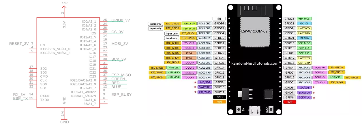
I am using a Seeeduino v4.2 with the VCC switched to 3V3. This is very important because the ESP32 module operates at 3.3V while the standard Arduino (ATMEGA328P) operates at 5V. Use level shifting circuitry to change the logic to 3.3V, otherwise the ESP32 module will not be able to connect to WiFi (status code = 6). However, if you already have the AirLift Coprocessor, it is already level shifted and should just work.
- DevKit IO18 - SCK
- DevKit IO14 - MOSI
- DevKit IO23 - MISO
- DevKit IO5 - CS
- DevKit IO33 - Pin 7 (BUSY/READY)
- DevKit EN - Pin 5 (EN) - LOW to reset
- DevKit Vin - 5V
- DevKit GND - GND
Install the Adafruit NINA library and run the scan and wifi client examples to ensure that the ESP module is working as expected. Note that the WiFi can take a while to connect.
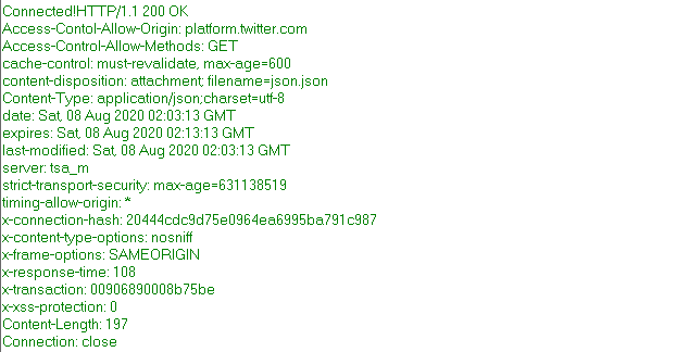
For the WiFiSecure example I decided to use the Bus Timing API to check that TLS was working as expected and I got back the JSON response! Happy times.
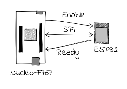
How the WiFiNINA communication works
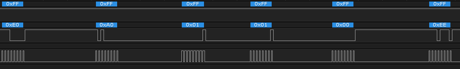
The SPI communication is structured roughly like I$^2$C, surprisingly. It first starts with a begin command: 0xE0, and ends with 0xEE. While SPI allows full duplex communications, the way that this is structured is in a half duplex mode: The master will send a set of commands to the slave over the TX channel while ignoring anything on the RX channel.
The master then waits for the slave to put the Ready pin high before it sends dummy data 0xFF over the TX channel and reads the input on the RX channel.
Porting
Now here comes the challenging part. The easiest way would be to use the HAL (Hardware Abstraction Library) SPI library to send and receive the SPI commands from the ESP32.
A HAL library is an abstraction that sits on top of the specific registers that the chip uses to control it's peripherals. Writing HAL code allows for portability because your code is no longer specific to how each device family choses to implement its registers. Different manufacturers have different approaches to writing HAL libraries: ST has a long track record of providing HAL libraries for their STM32 line and is always recommended to use them, whereas Silicon Labs is relatively skimpy on the HAL libraries, preferring to provide example code that uses register manipulation.
I decided to write my code on top of the HAL because this will open up the library to the rest of the STM32 family, and potentially other platforms that compile C++ code as well.
Porting the main library was a bit challenging because of the dependencies on the rest of the Arduino ecosystem, especially the reliance on IPAddress.h, however, I found that I could get away with recursively resolving all the dependencies within the ESP32 core library, which has some improvements over the ESP8266 core library.
Since the code was written in C++, I also had to convert the existing C project in STM32CubeIDE to C++, which is achieved by right-clicking the project and selecting Change to C++ project. Then the main.c has to be renamed to main.cpp.
Annoyingly when you change the configuration of the board, it still generates a main.c file instead of updating your main.cpp file, so you'll have to manually port the changes over. You can also encapsulate all your cpp code in another file, and call those functions into the main.c file.
FreeRTOS
Because I wanted to use FreeRTOS, which is only written for C, I had to make some changes to the generated code to ensure that it compiled. One major source of error was: sorry, unimplemented: non-trivial designated initializers not supported associated with the generated FreeRTOS default task:
osThreadId_t defaultTaskHandle;
const osThreadAttr_t defaultTask_attributes = {
  .name = "defaultTask",
  .stack_size = 128 * 4,
  .priority = (osPriority_t) osPriorityNormal,
};
This is resolved by filling in all the uninitiated values (in the same order as defined in the prototype!).
     const osThreadAttr_t defaultTask_attributes = {
    	.name = "defaultTask",
    	.attr_bits = osThreadDetached,
    	.cb_mem = NULL,
    	.cb_size = 0,
    	.stack_mem = NULL,
    	.stack_size = 128 * 4,
    	.priority = (osPriority_t) osPriorityNormal,
    	.tz_module = 0,
    	.reserved = 0
      };
The default stack size also has to be increased to prevent hardfaults.
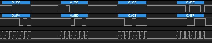
SPI Settings
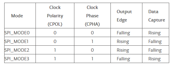
The settings for talking to the IC is: SPISettings(8000000, MSBFIRST, SPI_MODE0)
Unfortunately I had set the CPOL = 1 and CPHA = 1 Edge (CPHA = 0) in the STM32 configuration, and the number of bits is set to 4 by default when configuring the peripheral in STM32CubeIDE (needs to be 8), which is SPI_MODE2. If they are of different modes, they won't talk to each other.
Changing this was relatively easy in the STM32CubeIDE by modifying the .ioc file but it was very frustrating for the whole time where I thought I was sending the right commands, but in reality the clock polarity was wrong. This is where logic analyzers come in and Saleae makes the best ones on the market.
The SPI speed also has to be set equal or lower than 8Mhz, and I ended up using the prescaler to reduce the speed down to 6Mhz. Not ideal, but it works!
Success!
When I stepped through the code, it was able to print out the successfully connected message on the UART port, but the code hard-faulted after the first loop. The FreeRTOS stack size was set too small, so instead I decided to debug the code by using a superloop instead of an RTOS for now to make sure that the code was working.
And it was! I managed to get the blue LED on the Nucleo board to blink, and this meant that my code had successfully looped through once, connecting to WiFi and pinging the Adafruit test server.
Once I had the code working, I generalized the HAL-specific changes that I had to make so that the code could be used in other frameworks. This is useful because we can replace the HAL box with whatever we want. It can be another type of HAL library from another manufacturer, or even register manipulation. The great thing is that we don't have to figure out every detail of how the library works. As long as we know it's interfaces, we can use it.
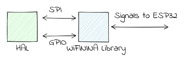
The WiFiNINA library is now completely encapsulated with no external dependencies. In order to use it, you will need to define the HAL-specific functions such as the code to trigger a change in the GPIO state, or how SPI signals are sent.
Problems
I used a USB Hub that wasn't powered, and when the WiFi chip turned on, it actually drew enough power to cause the board to reset. I didn't realize this until I heard the chime that Windows plays when something is disconnected, and it was happening whenever the chip started scanning.
I also included the WiFi.h into main.h, which is a C header file, and this caused the compiler to error out with messages about not recognizing extern "C". This was resolved by including the WiFi.h file into the main.cpp file.
I defined a few variables in a header file, causing linker issues. Resolved by defining them in the associated cpp file and using extern in the header file.