Better Soil Sensor
How a capacitive moisture sensor works with a 555 timer, and getting it to work with the BG22 Bluetooth chip from Silicon Labs!

I often get asked: "Ben, that soil sensor you used is too complex! I$^2$C for some capacitive sensing? Have you thought about using something cheaper?"
Literally no one has asked me this question, but that's okay.
Tldr; I found a a soil sensor that costs 10% of the first one I used and got it to work with the Bluetooth device from Silabs, BG22.
The Big Circle
Skip this part if you are not interested in origin stories.
Padauk's RFC Module
After learning about how the Adafruit Seesaw Soil Sensor worked, and as I was updating my Padauk post, I wondered if the Padauk microcontrollers actually had some sort of capacitive sensing capability.
Wouldn't it be great if I could actually make a cheaper soil sensor out of an ultra-cheap MCU? I could just read back the values via an analog signal. Armed with this curiosity, I went to Google and lo! I did thusly find some relevant information:
In the Padauk MCUs there is an RFC peripheral that can be used as a poor-man's capacitive sensor. The undocumented RFC peripheral is not described in the datasheet, but its existence was discovered by someone on eevblog:

For posterity's sake I'm including some of the information here. The datasheet that relates to this peripheral is as follows:
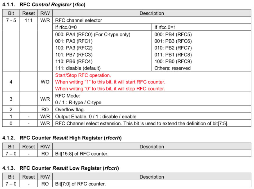
// Registers
__sfr __at(0x2d)          _rfcc;
__sfr __at(0x2e)          _rfccrh;
__sfr __at(0x2f)          _rfccrl;
#define RFCC              _rfcc
#define RFCCRH            _rfccrh
#define RFCCRL            _rfccrl

...

// To use the RFC

RFCC = 0xc0 | 0x08 | 0x02 ; // Select PB6, set to C-Mode, enable output

uint16_t result;
RFCC|= 1<<4; // start RFC
_delay_ms(50);
RFCC&=~(1<<4); // stop RFC
result=(RFCCRH<<8)|RFCCRL;However, one problem is that the Hackaday project uses SDCC (Small Device C Compiler) instead of the wonderfully obscure Mini-C that Padauk uses. I didn't have a device that could flash compiled SDCC binaries to Padauk MCUs, because at this point, SDCC is still at a point where users have to make their own flashing devices.
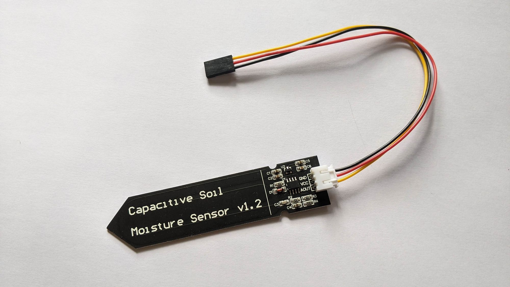
So as I was attempting to get this to work in Mini-C by adapting the code, I discovered that there is a whole host of capacitive sensors out there that are about a dollar each. On closer inspection, they are actually 555 timers in astable mode repurposed for capacitive sensing. I guess you can really make anything out of 555 timers!

Given that there is such a cheap option available, I decided to try it out.
How the cheap moisture sensor works
Electrobob wrote an excellent explanation about how the 555 capacitive sensor works. I've also included a video here from Andreas Spiess for those who are more inclined towards videos.
The 555 timer generates a square wave of around 500KHz. This is passed through a low pass filter that is made of the capacitive part of the soil sensor and a resistor. The output is then converted to an analog signal using a diode and capacitor rectifier.
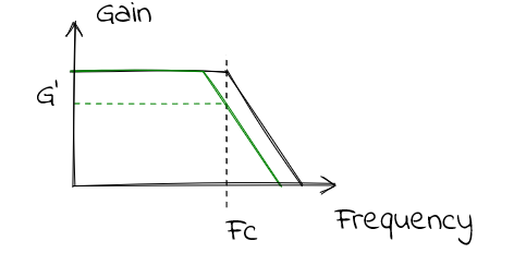
Imagine that the black curve was the initial state of the low pass filter and $F_{\text{c}}$ was the frequency from the 555 timer. At this point there is no attenuation to the signal.
Consider when the moisture content in the soil changes: the capacitance changes, which also changes the resonance frequency of the low pass filter. This is represented by a shift in the curve from black to green on the diagram. However, the output frequency of the 555 timer is still the same at $F_{\text{c}}$, therefore, the output gain is attenuated to $G'$. This is converted to a smaller analog signal, which is then picked up by the BG22 IC.
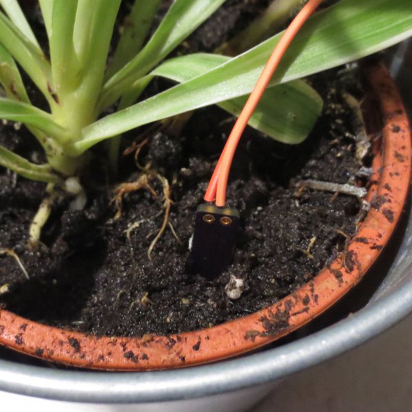
I decided to abandon my quest with regards to converting the Padauk MCU since there was a much cheaper analog solution available, and it works pretty well, the values remaining quite stable over time.
Fixing the high current draw
With the default circuit, the current draw is still quite high at around 6mA, and this is due to the NE555 timer IC, which requires about 6mA to operate. There is also a 5V to 3.3V LDO regulator on the board that I removed.
The NE555 timer IC can be replaced with a CMOS timer that draws about 200uA at max, which is a great improvement.
Finally, adding a transistor in line with the power of the soil sensor would help to further preserve power as the device will mostly be sleeping.
With these modifications, the circuit draws around 0.5mA when in operation and turns off when it is not being used.
Analog on BG22
 benlhy
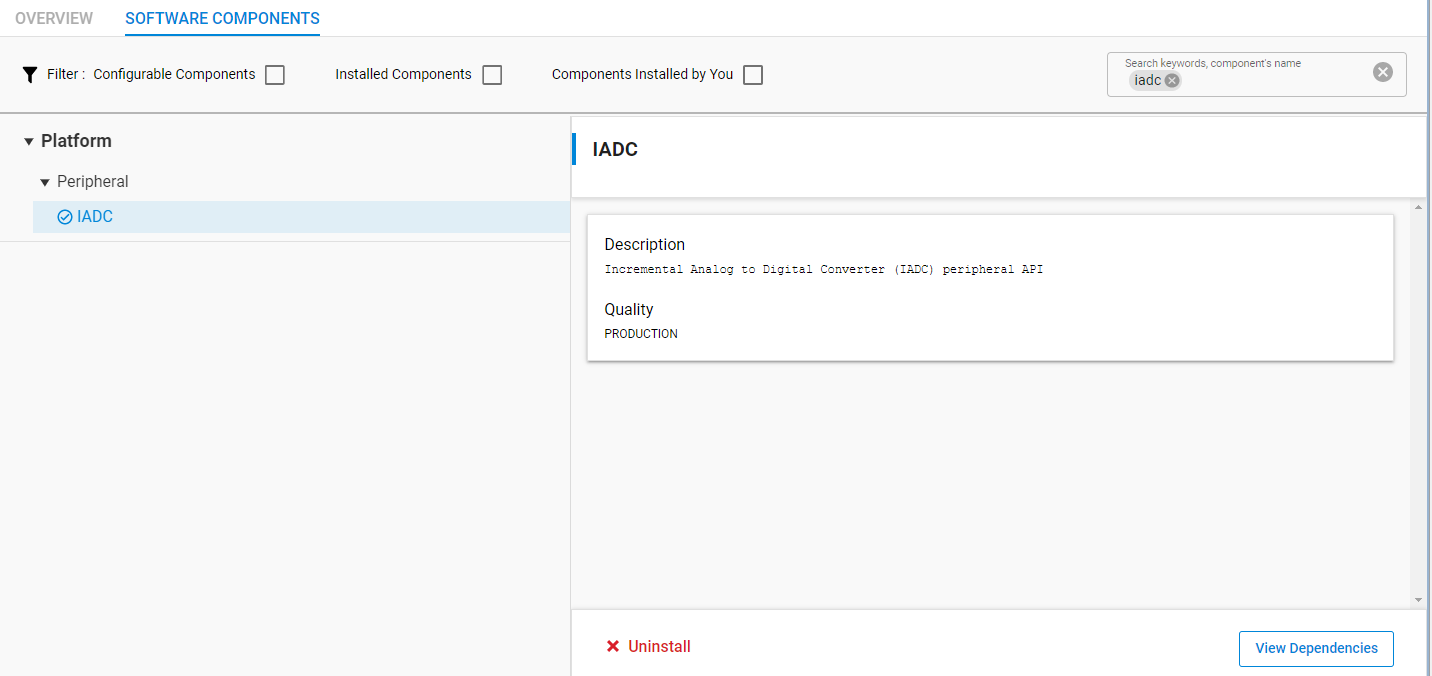
Getting the ADC to work on the BG22 was a little challenging as the examples were a little sparse. I have decided to document it here. For the BG22, if you are using Simplicity Studio, add the IADC software component into the project.
Include the appropriate header files into app.c
#include "em_iadc.h"
#include "em_cmu.h"
Add the appropriate definitions
// Set CLK_ADC to 10MHz (this corresponds to a sample rate of 77K with OSR = 32)
// CLK_SRC_ADC; largest division is by 4
#define CLK_SRC_ADC_FREQ        20000000

// CLK_ADC; IADC_SCHEDx PRESCALE has 10 valid bits
#define CLK_ADC_FREQ            10000000

// When changing GPIO port/pins above, make sure to change xBUSALLOC macro's
// accordingly.
#define IADC_INPUT_BUS          CDBUSALLOC
#define IADC_INPUT_BUSALLOC     GPIO_CDBUSALLOC_CDODD0_ADC0

// Stores latest ADC sample and converts to volts
static volatile IADC_Result_t sample;
static volatile double singleResult;
The IADC_INPUT_BUS define is required to expose the GPIO busses for the IADC module to access. Replace CD with the port that you are using, i.e if you are using PA7, then CDBUSALLOC would become ABUSALLOC because PA7 is on Port A. If the pin you are using is odd, then use GPIO_CDBUSALLOC_CDODD0_ADC0 or if it is even, use GPIO_CDBUSALLOC_CDEVEN0_ADC0.
Add in the initialization code and the code to handle the IADC reads. As I wanted to trigger single results, I decided to switch from IADC_pullSingleFifoResult(IADC0) to IADC_readSingleResult(IADC0). Another point to note is that the examples that are provided for IADC are for MG21, which has a 16 bit ADC whereas the BG22 has only 12 bits, so the parts of code that deal with the resolution have to be adjusted (bit shifting, and the number of valid bits).
If everything goes well, you should be able to read the measured voltage level as well as the counts on your favorite serial terminal.
Reference
Link to the cache: https://webcache.googleusercontent.com/search?q=https://hackaday.io/project/174822/logs