Neopixels with the SAMD10
Controlling WS2812b (Neopixel) LEDs with the SAMD10 in ATMEL Studio

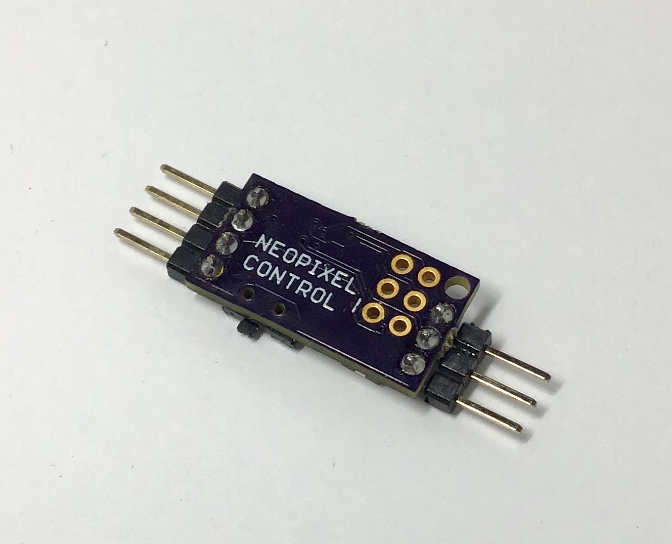
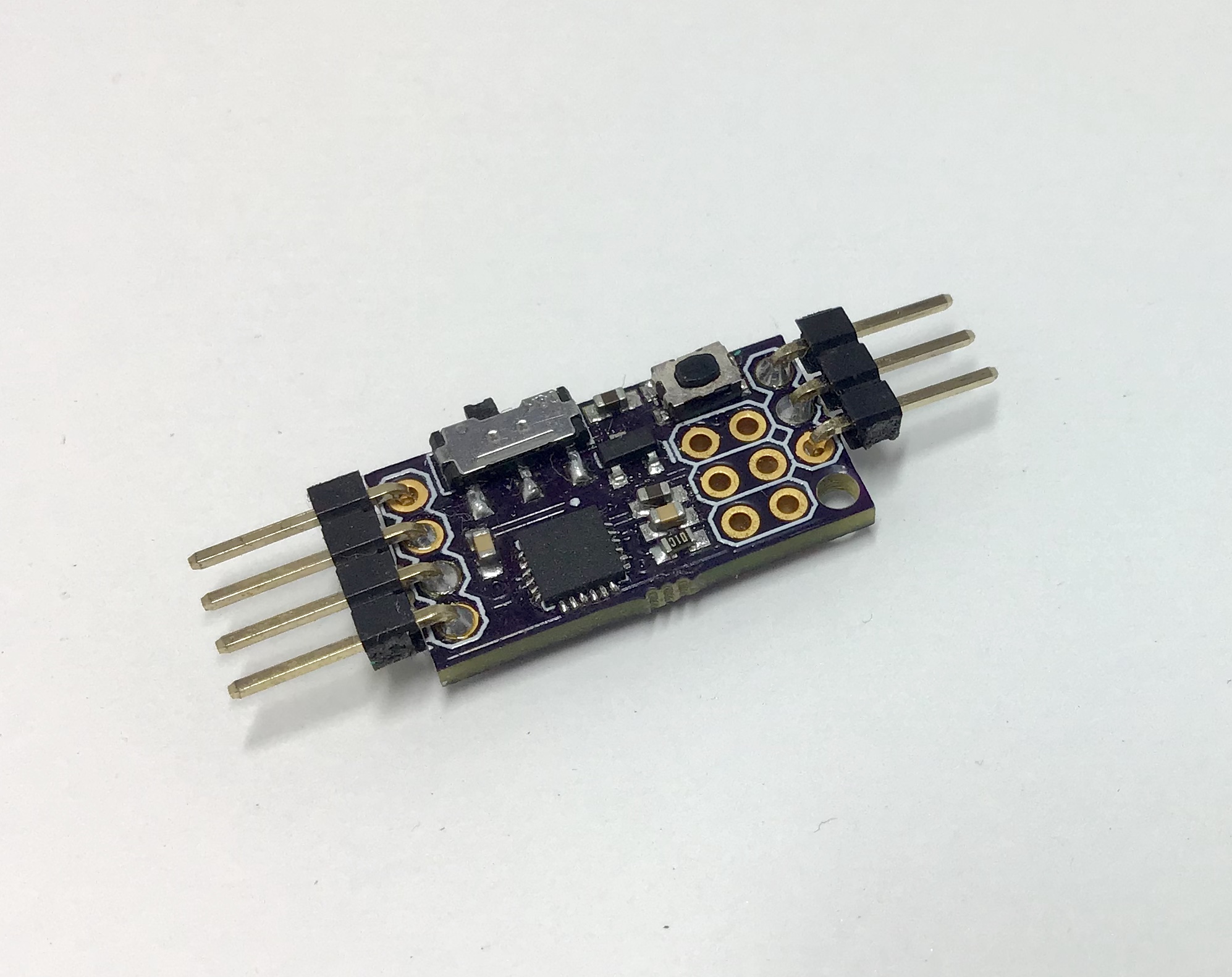
The SAMD10 is a Cortex M0 ARM chip that comes in an SOIC format. This makes it easier to solder and particularly attractive for small applications, since they are cheap (<$1!). The WS2812b, or the Neopixel, is an RGB LED that uses one data line to display 255 x 255 x 255 different colours/intensities. In this project, I managed to get the protocol to work on the SAMD10 chip.
What does it do?
It is a protocol to light a string of Neopixel RGB LEDs in C.
Why is it cool?
It has not been done before for the SAMD10. I implemented the protocol following some inspiration from others using first principles. The protocol has very strict timing requirements, so getting it to work on a tiny chip felt like an achievement. Plus, RGB blinkie animations!
Introduction
Getting started with this chip was easy. Using the SAMD10 Xplained board and Atmel Studio, I was able to get the usual gamut of communication protocols, LED togging and button mashing up and running.
One challenge I set for myself is to get the Neopixel, or the WS2812b LED to work with the SAMD10 chip. As far as I know, there have not been any libraries avaliable in Atmel Studio to get it to work. The WS2812b LED chip utilises a strict timing protocol to create a series of one-wire individually addressable RGB LEDs.
There are a few ways you can go around doing this:
- Use PWM to toggle the pins. However I found that changing the period of the PWM took too long.
- Manually toggle the pins. Josh Levine actually did some work on this and he determined that the minimum time to comply with the Neopixel timing is 500ns. I was able to get to 62.5ns per pulse, but I don't want to spend all my CPU power just toggling pins, especially if I wanted to include animations. Link to project
- Use SPI. This method is kind of complex, but it is doable. It basically exploits the fact that SPI has hardware that allows it to toggle pins much faster than a standard GPIO can. Link to project
After messing around with all three methods, I figured that using SPI was the most viable of the lot.
SPI setup
I used the Microchip SPI reference to get started on my project.
In order to use SPI to control the W2812b LEDs, the system clock must be set to 48MHz. This can be configured in conf_clocks.h.
/* System clock bus configuration */
#  define CONF_CLOCK_CPU_CLOCK_FAILURE_DETECT     false
#  define CONF_CLOCK_FLASH_WAIT_STATES            1
...
/* SYSTEM_CLOCK_SOURCE_OSC32K configuration - Internal 32KHz oscillator */
#  define CONF_CLOCK_OSC32K_ENABLE                true
#  define CONF_CLOCK_OSC32K_STARTUP_TIME          SYSTEM_OSC32K_STARTUP_130
#  define CONF_CLOCK_OSC32K_ENABLE_1KHZ_OUTPUT    true
#  define CONF_CLOCK_OSC32K_ENABLE_32KHZ_OUTPUT   true
#  define CONF_CLOCK_OSC32K_ON_DEMAND             true
#  define CONF_CLOCK_OSC32K_RUN_IN_STANDBY        false
...
/* SYSTEM_CLOCK_SOURCE_DFLL configuration - Digital Frequency Locked Loop */
#  define CONF_CLOCK_DFLL_ENABLE                  true
#  define CONF_CLOCK_DFLL_LOOP_MODE               SYSTEM_CLOCK_DFLL_LOOP_MODE_CLOSED
#  define CONF_CLOCK_DFLL_ON_DEMAND               false
...
/* Configure GCLK generator 0 (Main Clock) */
#  define CONF_CLOCK_GCLK_0_ENABLE                true
#  define CONF_CLOCK_GCLK_0_RUN_IN_STANDBY        false
#  define CONF_CLOCK_GCLK_0_CLOCK_SOURCE		  SYSTEM_CLOCK_SOURCE_DFLL
#  define CONF_CLOCK_GCLK_0_PRESCALER             1
#  define CONF_CLOCK_GCLK_0_OUTPUT_ENABLE         false

/* Configure GCLK generator 1 */
#  define CONF_CLOCK_GCLK_1_ENABLE                true
#  define CONF_CLOCK_GCLK_1_RUN_IN_STANDBY        false
#  define CONF_CLOCK_GCLK_1_CLOCK_SOURCE          GCLK_SOURCE_OSC32K
#  define CONF_CLOCK_GCLK_1_PRESCALER             1
#  define CONF_CLOCK_GCLK_1_OUTPUT_ENABLE         false
Here we drive the Digital Frequency Locked Loop with the internal 32.768kHz oscillator to get the main clock speed of 48MHz. Now that we have a high speed main clock, we can comfortably divide the main clock to get a baud rate of 2.5MHz.
#define BUF_LENGTH 2
#define SLAVE_SELECT_PIN PIN_PA17
#define CONF_MASTER_MUX_SETTING SPI_SIGNAL_MUX_SETTING_C
#define CONF_MASTER_PINMUX_PAD0 PINMUX_PA22C_SERCOM1_PAD0
#define CONF_MASTER_PINMUX_PAD1 PINMUX_PA23C_SERCOM1_PAD1
#define CONF_MASTER_PINMUX_PAD2 PINMUX_PA24C_SERCOM1_PAD2
#define CONF_MASTER_PINMUX_PAD3 PINMUX_UNUSED
#define CONF_MASTER_SPI_MODULE SERCOM1

struct spi_module spi_master_instance;
struct spi_slave_inst slave;


void configure_spi_master(void)
{
	struct spi_config config_spi_master;
	struct spi_slave_inst_config slave_dev_config;
	/* Configure and initialize software device instance of peripheral slave */
	spi_slave_inst_get_config_defaults(&slave_dev_config);
	slave_dev_config.ss_pin = SLAVE_SELECT_PIN;
	spi_attach_slave(&slave, &slave_dev_config);
	/* Configure, initialize and enable SERCOM SPI module */
	spi_get_config_defaults(&config_spi_master);
	config_spi_master.transfer_mode = SPI_TRANSFER_MODE_1;
	config_spi_master.mux_setting = CONF_MASTER_MUX_SETTING;
	config_spi_master.pinmux_pad0 = CONF_MASTER_PINMUX_PAD0;
	config_spi_master.pinmux_pad1 = CONF_MASTER_PINMUX_PAD1;
	config_spi_master.pinmux_pad2 = CONF_MASTER_PINMUX_PAD2;
	config_spi_master.pinmux_pad3 = CONF_MASTER_PINMUX_PAD3;
	config_spi_master.mode_specific.master.baudrate =  2500000; //2.5MHz  = 400ns per signal
	spi_init(&spi_master_instance, CONF_MASTER_SPI_MODULE, &config_spi_master);
	spi_enable(&spi_master_instance);
}
Here I will refer to a pulse as a state change from high to low or low to high, and a signal as a sequence of pulses that the WS2812b protocol recognises as 0 or 1.
Since each pulse is 400ns as we have defined as our baudrate for our SPI module, we need 3 pulses to indicate either 1 or 0 signals to the strip.
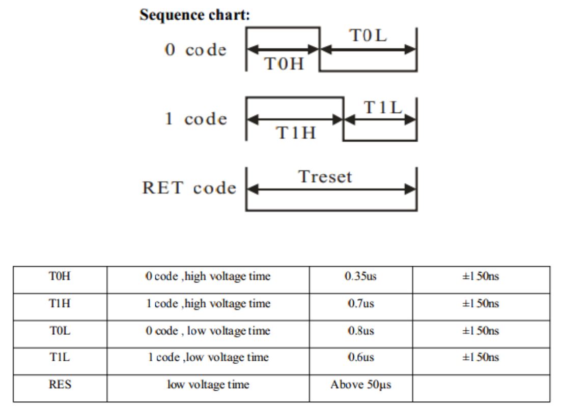
1. One high and two low pulse is zero
2. Two highs and one low pulse is one
Each 'bit' or signal, requires three pulses, and since there are eight bits per color, we need to send 24 pulses per color. Toggling this in software is not very fun, so a table is generated:
static const uint16_t bits[] = {
	0b100100100100, // 0000
	0b100100100110, // 0001
	0b100100110100, // 0010
	0b100100110110, // 0011
	0b100110100100, // 0100
	0b100110100110, // 0101
	0b100110110100, // 0110
	0b100110110110, // 0111
	0b110100100100, // 1000
	0b110100100110, // 1001
	0b110100110100, // 1010
	0b110100110110, // 1011
	0b110110100100, // 1100
	0b110110100110, // 1101
	0b110110110100, // 1110
	0b110110110110, // 1111
};
We break the eight bit signal up into four bits. However that still leaves us with 12 pulses that we need to send. These twelve pulses are broken up into two segments, one four pulse segment and a eight pulse segment. We can write functions to handle this for us:
static void spiSend(uint16_t cmd){
	while(!spi_is_ready_to_write(&spi_master_instance)){;}
	spi_write(&spi_master_instance,cmd>>8);
	while(!spi_is_ready_to_write(&spi_master_instance)){;}
	spi_write(&spi_master_instance,cmd);
}

static void sendByte (int value) {
	spiSend(bits[value >> 4]);
	spiSend(bits[value & 0xF]);
}
Writing Colors
Now we can write a wrapper function that sends an RGB value using the sendByte() function that we wrote. However, since the datasheet specifies that a minimum of 50us is needed before the chip starts to accept the incoming signal or to terminate it, we write a few empty bytes before and after to let the chip know that we are finished sending because our MOSI line idles high and we need it to be low to start.
static void sendRGB (int r, int g, int b) {
    spiSend(0);
	spiSend(0);
	sendByte(g);
	sendByte(r);
	sendByte(b);
	spiSend(0);
	spiSend(0);
}
That's it! Although you will have to use a SERCOM module to run the LED, there are still two left. The nice thing about this bitbanging technique is that it can be done on the fly without much memory, unlike Adafruit's library, where the entire sequence of bits is stored in memory before being sent out in one stream. Each time you send an RGB signal the data will be shifted into the next LED and it will light up.
Issues
It took me awhile to figure out how to set the correct clock rate for the SPI, and that the function spi_write() was only writing 8 bits instead of the full signal, so I had to split it up into two writes for the 12bit data from the table. Another problem that I faced was that the MOSI line was high once the transaction was complete. This complicated matters because the chip expects a low idle signal, but I fixed this by sending to extra bytes before my data to signal that a transaction is beginning and then a few extra bytes after to signal that the transaction is completed.
MOSI cannot idle low, only the clock pin can, I found out as I was trying to determine if changing the SPI mode would make any difference.
Why not use an Arduino?
I wanted to use a chip with a small form factor (QFN24) because I wanted to integrate it in-line with the strip itself. Plus this was a good opportunity for me to improve my familiarity with ATMEL SAMD10 ICs.
Wrapping it in Arduino
Furthermore, I have also updated the code with some wrapper functions that allow usage of Arduino library code. This allows the use of animation libraries that people have already written for the Neopixel. One particularly good example is LED Strip Effects. One advantage of this is that the ability to generate an 'image' for the entire strip before updating it. Previously, the code to animate the strip had to be generated serially on the fly. However, we have to store it in an array, so the code size scales with the number of LEDs that are being used, therefore, depending on your needs, you might or might not want to use this particular addition.
The ASF project is avaliable here: https://github.com/benlhy/W2812b-SAMD10
Implementation
I attached an LED strip to my bag and the board runs the Neopixels when power is supplied to it. This is good when I'm cycling or walking at night because it gets really dark. One improvement is to perhaps extend the strips to the side of the bag, so people approaching me from the side can see me as well.