Wayfinder System

Towards Better Biking Safety
Background
I met the excellent Signals team at Maker Faire Singapore in July. They were developing the product The Official Signal.
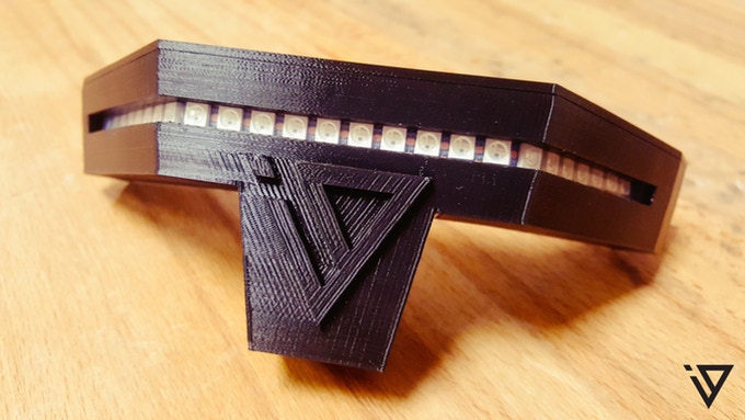
Figure 1. The Official Signal
It appears to be a motion-sensing bike attachment. From what I could tell the detection was based on detecting a spike in acceleration when the user turns their head, and this turns on the light. While they were not able to share the details of their platform with me because it was proprietary, I did gain a few important ideas from talking to them.
- Helmets are important. Helmets have mounting spaces.
- Attachments instead of integrations
Original issues with Wayfinder Glove
Sewing in a 3D space is not an easy task because you have to avoid stitching two sides together. However, the attachment that the Signals team used can be removed from the helmet and it set me to thinking. I could create a piece of cloth that can be added by wrapping around of the original glove and held in place by velcro. Doing so would solve a number of problems:
- Washable
I was always nervous about washing my electronics, even if they were washable. By being able to remove the electronics will enable the glove to be washed without endangering the electronics. - 2D
The piece of cloth would be 2 dimensional and allow for easier sewing.
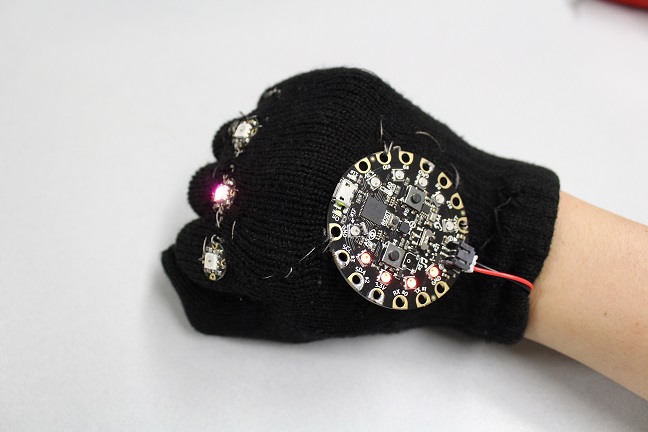
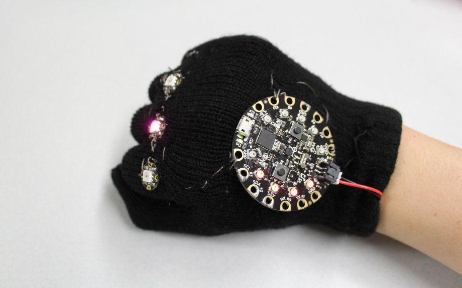
Figure 1. The Wayfinder Glove
The idea of a helmet also opened up a number of possibilities. It allowed for a bigger system than a glove. I saw a problem with the Signals helmet: when I reach an intersection, I would look left and right. However the system would interpret it as a left signal, then a right signal. When I cycle, I usually look ahead even when turning and don't move my head around much, so the utility of activating the helmet by looking around is lost on me.
My solution is to integrate the Wayfinder Glove and the Signals Helmet. They can communicate via a wireless protocol. The signals will be activated by the Wayfinder glove. If I reach out my hand to indicate I am turning, the helmet will also echo with an appropriate signal. If I brake, the helmet will automatically flash red, and turn off when I accelerate. My helmet would be run off a BLE SoC with Arduino support. It will integrate an accelerometer, a charger, a Neopixel strip, and a li-poly battery for charging, as compared to the 9V battery that the Signal Team uses.
The Way Forward
So the task ahead is twofold: develop a wireless module capable of running the Wayfinder Helmet, upgrade the Wayfinder Glove to be an attachment, and add wireless support to the Wayfinder Glove.
A custom board for the Wayfinder Helmet can probably be made to integrate the accelerometer and the SoC chip.
A new board for the Wayfinder Glove will probably have to be made for a SoC chip instead of a Cortex M0 chip, which is really overkill for a task like this.
I believe the nrf52832 is a suitable chip for the main SoC, or it can be a 24L01+ module with a Arduino chipset. Instead of using the BLE stack, I am using the proprietary 2.4Ghz Nordic radio because the communication does not need to be secure and it does not have to transmit too much information. The glove itself only has three states: right, left, resting. So it only has to transmit 3 numbers to the other module to let it know the status. This communication can be one way because the helmet doesn't need to respond. This would be even easier with a 433 MHz transmitter and receiver but I decided against it because they were unreliable in my experience.
I was able to get two nRF52832 chips to talk to each other using the proprietary 2.4GHz Nordic protocol. The problem is that the nRF52832 is a 3.3V chip, but the Neopixel is a 5V device, so some level shifting is required to get it to work. However I do not anticipate any large problems. Once I integrate the LSM303 with the nRF, I can mount it on a sewable board. The hand will require a portable power supply, but the helmet can be used with a standard battery pack.
Version 1 problems
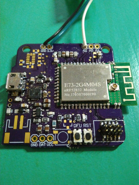
I soldered on the board and after a few false starts I discovered that for some reason, my ground planes were not properly routed, resulting in the following black wire being necessary to connect the ground plane of the nRF52 chip to the ground plane of the board.
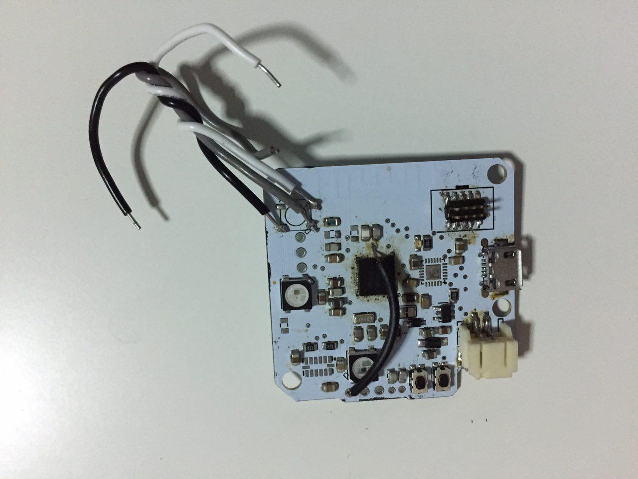
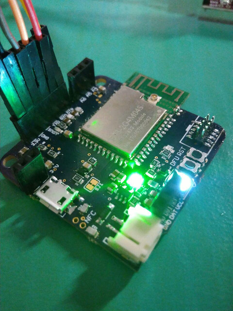
Even so the board did not work, and the LED that was used to indicate messages were being received remained solidly green. I also discovered that the WS2812b were not lighting up and this might also have been a grounding issue. However it worked when I included a logic level converter from the 3.3V nRF52 to the 5V data line of the WS2812b.
The next version has two different updates. It will use a module, removing any RF headaches.
Version 2 problems
I soldered the module on the updated board. However, I was not able to get the CP2104 module to work. It could be that the USB connector was overheated as seen by the tarnished surface. The first CP2104 module that I tried had a short and I burnt it out. The second module did not respond when I plugged it in and running lsusb did not even list it as being detected.
The next version will remove the onboard CP2104 module in favor of using a prebuilt module. This not only saves time on my part in soldering on the QFN module, but it also reduces the cost since I don't have to support the circuitry of the CP2104 chip, making it a more compact design. Granted that this would be a very scaled back version of my original vision, but at this point I would just like the board to work.
Version 3
The version 3 system works perfectly. The onboard Neopixel is confirmed to work, as is the compass sensor. The RX and TX lines were swapped on the CP2104 module, so RX on the CP2104 should really connect to the RX on the nRF52. I discovered this my reading the documentation on the STM32udino wiki on flashing Arduino to the boards.
The next version of the board will focus on reducing the size of the board by placing components under the board and using 0603 sizes for the resistors and capacitors.
Now that the board works, we can start focusing on the integration of the sensors and working on the BLTE application.
Mounting
I decided to mount the light strip onto my bag because I carry it around with me most of the time, whether I need it or not.
Software
Other ideas
If you layer the top with a piece of cloth and sew through it instead of the layer, the layer now becomes an insulating piece and you can cross two lines on a 2.5D space.