Arduino DIY Sunrise alarm clock
I built a sunrise alarm clock in Arduino.

I have trouble waking up on gloomy winter days. Hearing so much about the Philips Wake-Up alarm made me wonder how hard it was to build one given its rather high price.
Turns out, it wasn't very hard or expensive.
I've always wanted to build one of these:

There are many (claimed) benefits to having a Sunrise or Wake-up light, one of which includes a gentler wake-up as compared to the loud buzzing of an alarm in the darkness (true). I noticed that I often would shut off the alarm and go back to sleep, and waking up was kind of rough.
One of these things at the moment costs $49.99 (with a $20 coupon applied). A more expensive version with a colored sunrise simulation costs $139.99. That is a little more expensive than what I want to spend on a light that gradually lights up in the morning.
I don't have the capability to manufacture something like that, but I am able to mess around with LEDs, and I figured a better way to do this than having a morning light is actually simulating sunrise: make it so that my window lights up as if it was daylight outside.
I can have morning at whatever time I want.
There are also other projects that aim to create some sort of artificial light. The Smart LED window creates a sunlit basement.

So this proves that using LED behind blinds can actually create a nice simulation of daylight. This project uses a Raspberry Pi to control the lights, and turn them on and off as required.
However, using a Raspberry Pi in my case is kind of an overkill because I want to wake up at the same time every day. So instead, I used an Arduino Pro Mini (5V) that was being sold for $4 in Microcenter. I also happen to have a 5m strip of warm LEDs that I bought off AliExpress for $4.41. I needed a IRLB8721 MOSFET ($1) to control the brightness and the current, and finally some breadboard wires, a DC female plug and a 12V DC charger ($5) to complete the package. I used a DS1307 module pictured here, and you can buy one off AliExpress for about $0.50. CR2032 batteries should cost $1 each.
WARNING: The DC plug pictured below is not the one on an Arduino UNO board. That is designed only to power the board and is not capable of withstanding the large current draw the window needs.
WARNING: An Arduino Pro mini clone might not be able to take in 12V. Check the rating on the board. The safest solution is to use a 5V regulator before connecting to the RAW input pin.
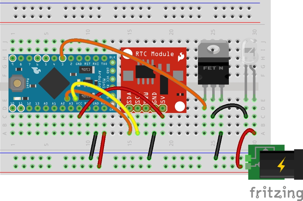
The board is powered by supplying 12V from our wall plug to Vin of the Arduino board you are using. Make sure that your board can take in 12V or you will need a step down regulator for your board.
The gate of the MOSFET goes to pin 3 of our Arduino so that we can use PWM to modulate how much current gets sunk, and in return, how bright the LEDs are. Here we are simulate a LED strip with an LED. If you have an LED strip, just connect the positive and negative leads to the strip as in the LED pictured above.
The sketch itself is pretty simple. Check the time, if it is the time, increase the light. I used 5 seconds as my time in-between increments, which works out to 20 minutes to increment the light to full brightness.
This code includes functionality for a switch that is connected to pin 2. It must be pulled up By using the switch you should be able to turn it off. You'll have to connect an SPDT switch to GND and VCC on both ends. The middle of the switch should go to Pin 2. I settled for unplugging it in the morning.
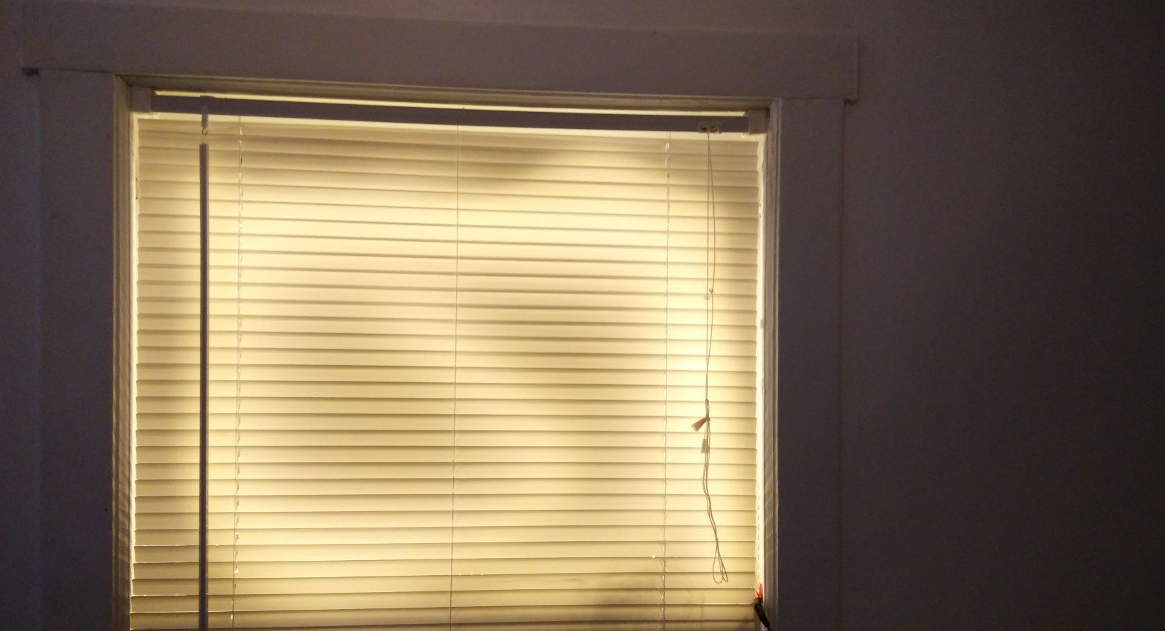
For now I've just sticky-taped the entire thing to my window to prototype the effect, but once it is finalised I will probably transition it to a nicer/portable design.
Total cost comes out to about $20, which is savings of about 50% if we are comparing it against the sunrise alarm clock after discount. It was a good learning experience and this alarm is programmable and extensible. So I'd say it is a pretty good deal.
The benefit of this particular alarm is that it creates the effect of the sun naturally, so the sun always "sets" and "rises" at the same time in the room by adjusting how much light fades in at what time.

The LEDs bright and dark spots don't show as much as seen in the image. I turned the LEDs inwards to create a softer glow. With a longer strip I might have been able to eliminate the dark spots, but honestly it isn't that big of a deal. Note that outside was completely dark.
Putting it together took about 3 hours, 2 of which was figuring out why my RTC module didn't work (slipshod soldering on my end). Putting the next one together would probably take me about an hour.
I tried to use a gauze cloth to diffuse the lights. If your LEDs are right up against the blinds they don't diffuse well. But it turns out that you need a significant layer before you get any kind of diffusion. It might be better to get a piece of frosted plastic and bounce the light off it.
Usage
After about 3 days I am starting to wake up at 6am, when the alarm is fully bright.
After about two weeks of use I wake up at approximately 630am, but lie in bed until my phone's alarm goes off.
I have not used it this winter and my sleeping habits have shifted to waking up at 10am. Once I started using it, my waking hours have shifted to 8am and earlier. I think just having a light in the room is incentive to wake up. But because it fades in, it is not as harsh as flicking on a light in the room, and since it is not directly above me, I have the option to wake up slowly.
After a long period of using this alarm, I managed to successfully shift my waking time from 730am to 715am.
I noticed that when I wake up without the light alarm, I am always groggy. But with the light alarm, even if I don't wake up at 715am, I'm almost never groggy.
Sketch
#include <RTClib.h>
#include <Wire.h>

#define LEDPIN 3
#define SWITCHPIN 2

#define HOUR 5
#define MINUTE 30

#define FADESPEED 5000

RTC_DS1307 rtc;

bool light_up_now = false;

void setup()
{
  pinMode(LEDPIN, OUTPUT);
  pinMode(SWITCHPIN, INPUT);
  Serial.begin(57600);
  if (! rtc.begin()) {
    Serial.println("Couldn't find RTC");
    while (1);
  }

  if (! rtc.isrunning()) {
    Serial.println("RTC is NOT running!");
    // following line sets the RTC to the date & time this sketch was compiled
    // rtc.adjust(DateTime(F(__DATE__), F(__TIME__)));
    // This line sets the RTC with an explicit date & time, for example to set
    // January 21, 2014 at 3am you would call:
    // rtc.adjust(DateTime(2014, 1, 21, 3, 0, 0));
  }
}

void loop()
{
  DateTime now = rtc.now();
  if (digitalRead(SWITCHPIN) == HIGH) {
    // turn off the light if swich is in OFF position
    analogWrite(LEDPIN, 0);
  }
  if ((now.minute() == MINUTE) & (now.hour() == HOUR)) {
    // wake up now
    light_up_now = true;
  }
  else {
    // wait for one second
    delay(1000);
  }
  // if the switch is on, and the switch is in the ON position
  if (light_switch == true & digitalRead(SWITCHPIN) == LOW) {
    for (int i = 0; i < 256; i++) {
      analogWrite(LEDPIN, i);
      delay(FADESPEED);
      if (i == 254) {
        light_up_now = false;
      }
    }
  }
}
Adding an LCD screen
Rebuilding the alarm is a hassle on a breadboard with wires and jumper cables flying everywhere, so I am building a new board that takes care of all of that for me, so all I have to do is to is to plug in the LED strip and run a program for it to work.
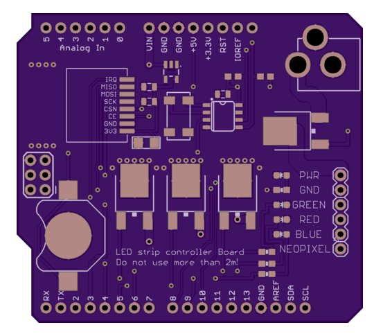
This board also includes space for an nRF24l01+ SMD radio, which allows remote communication with the Arduino using the nRF24 protocol.
I did not include a switch on this design because it might be located somewhere else other than on the board.
Adding an LCD eats up most of the remaining pins on the Arduino, but I think this is a good addition. Note that in order to print integers and strings, you will need to set the LCD's cursor manually each time you are changing from an integer to a string or vice versa.
The contrast pin VO is can be set with a 10K potentiometer. An alternative is to use 10k and 1k resistors as a potential divider. It worked as well as the 10k potentiometer for my setup.
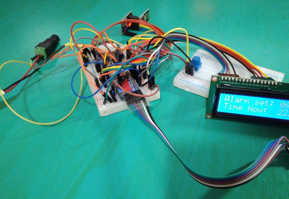
Note how messy it is! Doing this via breadboarding is not suggested. Instead, use either a perfboard or use the shield to reduce the tangle of wires. The following Fritzing diagram is provided for the ease of prototyping.
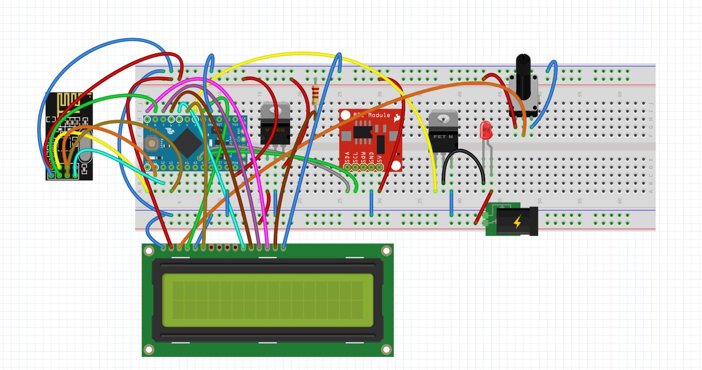
Note that the nRF24 chip is actually hooked up to 3.3V voltage regulator, then to the 5V power rail. The voltage regulator is not included here for simplicity.
TO DO
The following are a series of possible additions to the alarm.
- Use white LED lights instead of warm white. Warm white gives off the color of sunset, not a sunrise.
Use a gauze cloth to diffuse the light- Use a piece of frosted plastc to diffuse the light
Ability to set time remotelyMove everything off a breadboard.- Add sound
- Add PIR Sensor
- Look into super bright LEDs
- Look into LED lamps