Sunbar

The SunBar is light alarm, following my development of light-based alarms which I have found to be quite effective in establishing a set routine of waking up early. The earlier versions were based off: a breadboarded circuit, a protoboard circuit with an ATTiny85, and an Arduino Shield.
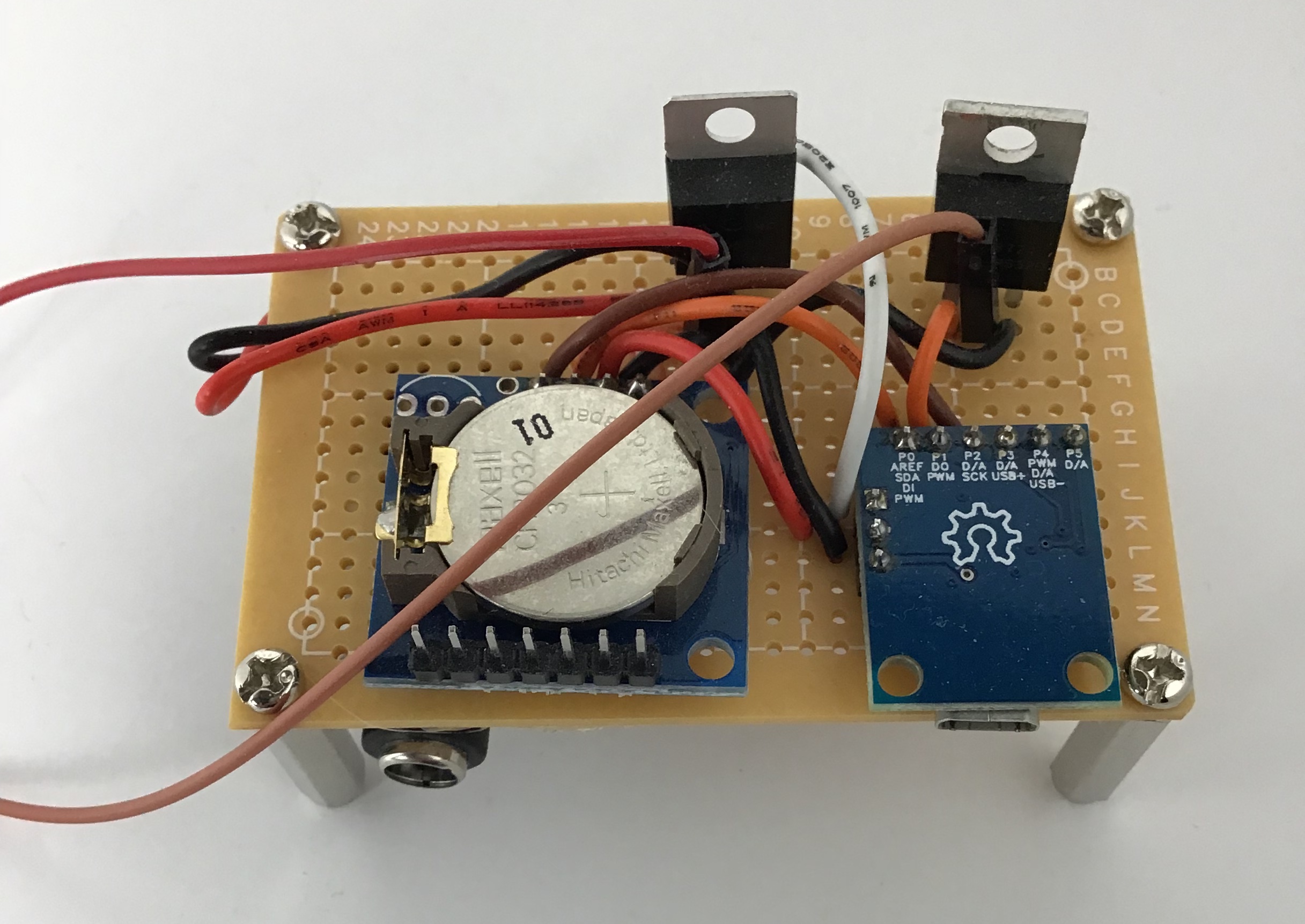
The protoboard version was designed to take 12V and regulate it down to 5V for the ATTiny85. A N-Channel Mosfet was used to control the brightness of the LED strip.
This new version is designed to be as compact as possible, and fit within a case. I found that the adhesive on the backs of the LED strips to be poor at best, and they usually fell off after about two weeks or so. However, I continued to use it because it was still effective, even as a heap at the bottom of the window.
One back-end change to the design is that it is all made in KiCad, which makes modelling particularly enjoyable because it generates a 3D model of the PCB and components. While KiCad itself has a limited selection of 3D models compared to the footprints available, I found GrabCad to be an excellent resource in closing the gap. The model can also be exported as a Step file, which can then be read by other 3D modelling software like Solidworks.
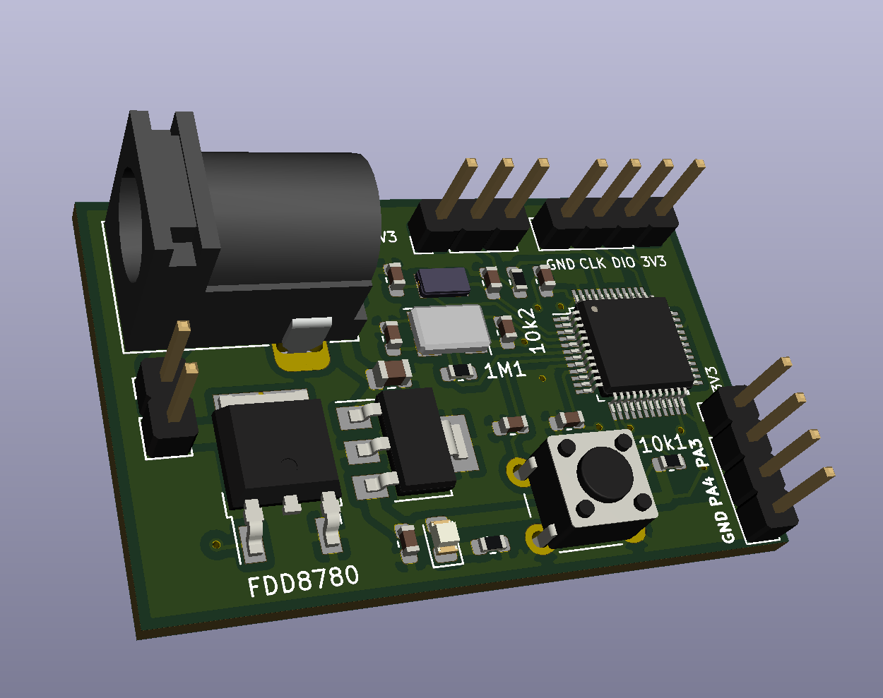
Another big change is that the microcontroller is now an STM32 part instead of an Atmel part. I really enjoy programming with STM32 and the cheapest part, the STM32F030F4P6, comes in a nice, hobbyist friendly TSSOP package. I noticed that STM tends to favor TQFP designs rather than the harder-to-solder parts like QFN or BGA chips which have leads under the package, so it might be a good choice if you do a lot of assembly yourself. Because I have always assembled my boards by hand, and the time saved in soldering exposed pins is quite considerable.
Version 1
Version 1 used the STM32F030C8T6 chip, which is a 48 pin QFP package. A lot of pins were left unused. However, because of a mistake in wiring the programming headers, despite repeated attempts at a white wire fix, the chip could not be programmed so testing moved on to the FDD8780 N-channel MOSFET. It was found that the wiring was correct and the behavior of the LEDs was as expected.
Version 2
Version 2 uses the cheapest chip available as an STM32 part. The STM32F030F4P6 chip is a TSSOP part with 20 pins.