Proving Fields
Test your mettle against this board!

What is it?
It is a PCB that has components mounted on to test the understanding of protocols like blinking an LED, using interrupts, and communication protocols like I2C and SPI.
Why is it cool?
Getting to know a chip almost always follows the same process: Blink an LED, read a button, use SPI/I$^2$C, get a screen to work. I realised that I was building the same circuits over and over again on the breadboard, so I decided that I wanted a more permanent solution.
Introduction
This project was derived from an earlier project. It was originally meant to be a field testing kit where it would help me to determine current draw, and test communication protocols. However, after designing the entire board and sending it off to be manufactured, I took a step back and asked if I really needed such a board. It turns out that I didn't:
- Not sure of what SPI/I$^2$C protocol to test or how to test it
- I will probably have my computer and a nearby board to test it with
- Already a product: SPIDriver
Thinking about it closer, what I didn't need was an SPI driver/tester, but a permanent fixture to test my SPI protocols on. Thusly the Field Testing Kit (FDK) was depreciated and the Do You Know Your Chip? Kit (DYKYC?K) was born. Okay that was quite a mouthful, the name is still a work in progress. EDIT: The name has been changed to Proving Fields.
This post also serves as a quick and dirty introduction to using the Atmel Software Framework (ASF) to program protocols such as SPI and I2C.
Design
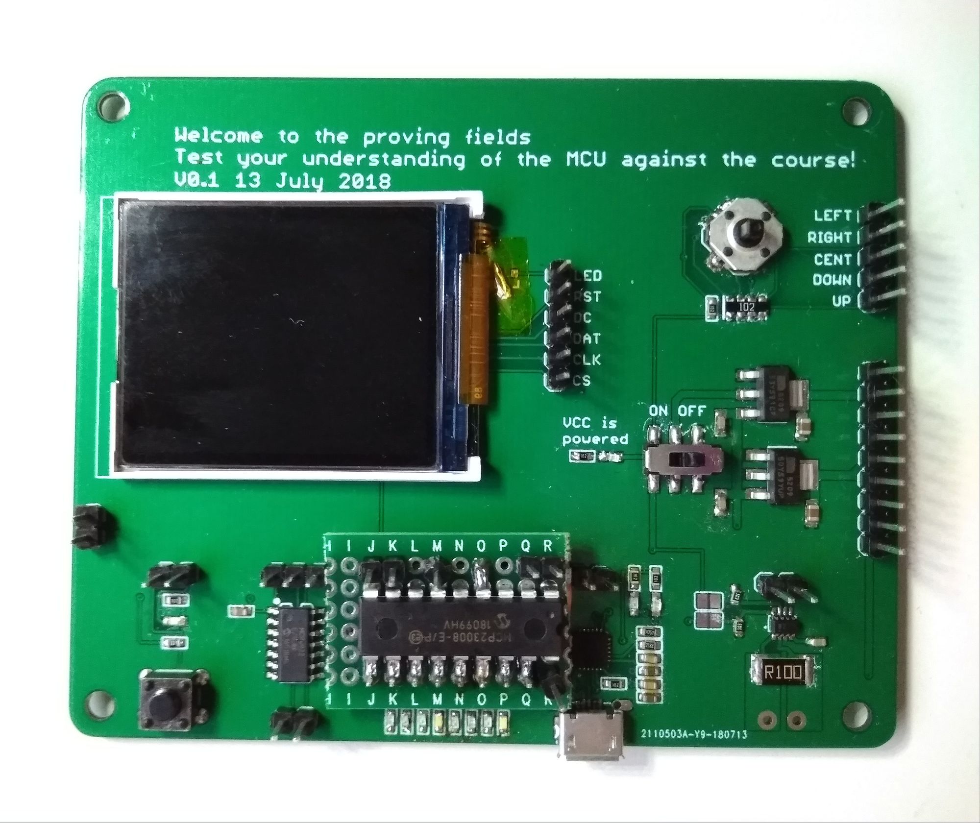
This board sports the following features:
- Blink an LED (pin toggling)
- Button press (read pin)
- 5 Way Tactile Button (interrupts)
- TFT LCD/DAC, MCP4922 (SPI)
- I/O Expander, MCP23008 (I2C)
- CP2102N UART-to-USB (UART)
- TFT LCD (SPI)
- Current Sensing (I2C)
- Power supply (3.3V and 5V)
The SPI and I2C chips were chosen because they are relatively simple to control and output directly measurable signal. In the case of the MCP23008, it resets to the default state of all GPIO inputs, so if a high output was configured over I2C, this would clearly show up on a measurement. For the DAC, setting a voltage halfway between 3.3V and 0V would clearly demonstrate control over SPI.
The TFT LCD and the current sensing are both useful components, but they also provide an additional challenge beyond simple pin toggling. Finally, a power supply circuit is also provided as an additional option to power the board. It provides both 3.3V and 5V. A USB can be connected to the board, and the USB and V pins can be connected to supply power to the voltage regulators. Note that the VCC line should not be connected to avoid bus contention.
Final Assembled Product
Quickstart
To get you started quickly, I am providing the following code as reference. The code was tested using an ATMEL SAMD21 Xplained Pro. The code provided for the Quickstart guide uses the Atmel Software Framework (ASF) in Atmel Studio. It is assumed that the user has had some familiarity with using ASF, or if not, a new project should be created, and in the ASF Wizard, the appropriate modules should be added.
MCP23008, GPIO Expander (I2C Master, polled)
The following code uses PA05 as the reset toggle pin, PA08 as the SDA, and PA09 as SCL. SERCOM2 is used for I2C. This code will turn GP0 into an output pin and set it to high, demonstrating that I2C communication with the MCP23008 is working.If the toggle pin is not required, then it should be tied to high.
#include <asf.h>

#define DATA_LENGTH 2

#define OLAT 0x0A // output latch
#define IODIR 0x00 // direction of data I/O
#define GPIO 0x09 // Read current state of each pin

static uint8_t my_buffer[2] = {IODIR, 0xFE};

static uint8_t read_buffer[DATA_LENGTH];

#define SLAVE_ADDRESS 0x27

#define TIMEOUT 1000

struct i2c_master_module i2c_master_instance;

void configure_i2c_master(void);
void reset_slave(void);
void mcp23008_setup(struct i2c_master_packet packet);

void configure_i2c_master(void)
{

	struct port_config pin_conf;
	port_get_config_defaults(&pin_conf);

	/* Configure LEDs as outputs, turn them off */
	pin_conf.direction  = PORT_PIN_DIR_OUTPUT;
	port_pin_set_config(PIN_PA05, &pin_conf);
	port_pin_set_output_level(PIN_PA05, true);


	struct i2c_master_config config_i2c_master;
	i2c_master_get_config_defaults(&config_i2c_master);

	config_i2c_master.buffer_timeout = 10000;
	config_i2c_master.baud_rate = I2C_MASTER_BAUD_RATE_400KHZ; // at 3.3V, the default i2c baud rate for the MCP23008 is 400kHz

	i2c_master_init(&i2c_master_instance, SERCOM2, &config_i2c_master);

	i2c_master_enable(&i2c_master_instance);
}


void reset_slave(void){
	port_pin_set_output_level(PIN_PA05, false);
	delay_ms(1);
	port_pin_set_output_level(PIN_PA05, true);
}

void mcp23008_setup(struct i2c_master_packet packet){
	reset_slave();
	static uint8_t temp[2];
	temp[0] = IODIR; // direction of pin
	temp[1] =  0xFE; // last pin output, all input
	packet.data = temp;
	i2c_master_write_packet_wait(&i2c_master_instance, &packet);
	temp[0] = OLAT; // output latch
	temp[1] = 0x01; // last pin high
	packet.data = temp;
	i2c_master_write_packet_wait(&i2c_master_instance, &packet);
}

int main (void)
{
	system_init();
	delay_init();


	configure_i2c_master();

	uint16_t timeout = 0;

	struct i2c_master_packet packet = {
		.address     = SLAVE_ADDRESS,
		.data_length = 2,
		.data        = my_buffer,
		.ten_bit_address = false,
		.high_speed      = false,
		.hs_master_code  = 0x0,
	};

	mcp23008_setup(packet);

	while (1) {
		/* Is button pressed? */
		if (port_pin_get_input_level(BUTTON_0_PIN) == BUTTON_0_ACTIVE) {
			/* Yes, so turn LED on. */
			port_pin_set_output_level(LED_0_PIN, LED_0_ACTIVE);

		} else {
			/* No, so turn LED off. */
			port_pin_set_output_level(LED_0_PIN, !LED_0_ACTIVE);
		}
	}
}
MCP4922, Digital to Analog Chip (DAC) (SPI master, polled)
I used the ASF Reference for the SPI pinmux configuration. This code uses PA04 as MOSI, PA05 as SCK and PA17 as the CS. You can use any pin as the Chip Select (CS)/Slave Select (SS).
This code sets an arbitary output on channel A other than zero which can be observed using a multimeter.
#include <asf.h>

// ***** spi ***** //

// SPI uses SERCOM0
// Configuration A
// 0 MOSI : PA04
// 1 SCK  : PA05
// 3 SS   : PA17


#define BUF_LENGTH 2


struct spi_module spi_master_instance;
struct spi_slave_inst slave;

static uint8_t buffer[BUF_LENGTH] = {
	0xFC, 0xF0
};

void configure_spi_master(void)
{
	struct spi_config config_spi_master;
	struct spi_slave_inst_config slave_dev_config;
	/* Configure and initialize software device instance of peripheral slave */
	spi_slave_inst_get_config_defaults(&slave_dev_config);
	slave_dev_config.ss_pin = PIN_PA17;
	spi_attach_slave(&slave, &slave_dev_config);
	/* Configure, initialize and enable SERCOM SPI module */
	spi_get_config_defaults(&config_spi_master);
	config_spi_master.mux_setting = SPI_SIGNAL_MUX_SETTING_A;
	config_spi_master.pinmux_pad0 = PINMUX_PA04D_SERCOM0_PAD0;
	config_spi_master.pinmux_pad1 = PINMUX_PA05D_SERCOM0_PAD1;
	config_spi_master.pinmux_pad2 = PINMUX_UNUSED;
	config_spi_master.pinmux_pad3 = PINMUX_UNUSED;
	//config_spi_master.mode_specific.master.baudrate = 3000000;
	spi_init(&spi_master_instance, SERCOM0, &config_spi_master);
	spi_enable(&spi_master_instance);
}

void set_output(uint8_t pin, uint16_t value){
	static uint8_t temp[2];
	if (pin==1){
		temp[0]=(0b0011<<4)|(value>>8);
		temp[1]= 0b11111111 & value;
	}
	else {
		temp[0]=(0b1011<<4)|(value>>8);
		temp[1]= 0b11111111 & value;
	}
	spi_select_slave(&spi_master_instance, &slave, true);
	spi_write_buffer_wait(&spi_master_instance,temp,2);
	spi_select_slave(&spi_master_instance, &slave, false);
}

int main (void)
{
	system_init();
	delay_init();

	configure_spi_master();
	set_output(1,160);

	while (1) {
		/* Is button pressed? */
		if (port_pin_get_input_level(BUTTON_0_PIN) == BUTTON_0_ACTIVE) {
			/* Yes, so turn LED on. */
			port_pin_set_output_level(LED_0_PIN, LED_0_ACTIVE);
			set_output(1,160);

		} else {
			/* No, so turn LED off. */
			port_pin_set_output_level(LED_0_PIN, !LED_0_ACTIVE);
		}
	}
}
TFT LCD, ST7735, SPI
Getting the LCD to work can be a little annoying, so some work derived from Adafruit's fine ST7735 library is used to get the screen to work.
A short explanation is that this screen uses the SPI module to send information
The file is a little too big so this is a link to the Github page that contains code for the LCD. Provided here is some starter code that turns the screen red when you press the button on the Xplained board. The ASF modules of SPI (Polled), and Delay have to be added before the code can be compiled.
If the delay is not working, check that delay_init() was added. For the SAMD10, the internal 8Mhz oscillator was used to drive the 48Mhz Digital Frequency Locked Loop (DFLL), which is configured in conf_clocks.h. Check that CONF_CLOCK_FLASH_WAIT_STATES is set to 1.
For the SAMD21 Board
MOSI: PA4, SCK: PA5, DC: PA16, CS: PA17, RST: 3.3V, LED: GND.
For the SAMD10 Board
MOSI: PA22, SCK: PA23, DC/AO: PA16, CS: PA17, RST: 3.3V, LED: GND
#include <asf.h>
#include "lcd.h"

int main (void)
{
	system_init();
	delay_init();
	configure_port_pins();

	LCD_init();
	LCD_clearScreen(BLACK);

	while (1) {

		if (port_pin_get_input_level(BUTTON_0_PIN) == BUTTON_0_ACTIVE) {

			port_pin_set_output_level(LED_0_PIN, LED_0_ACTIVE);

			LCD_clearScreen(RED);
		} else {

			port_pin_set_output_level(LED_0_PIN, !LED_0_ACTIVE);
		}
	}
}
5 Way Tactile button, interrupts
I thought that having the screen change colour would be a pretty striking indication that the device is working. When you press the button, the screen turns red. It uses PB11 as the trigger pin.
#include <asf.h>
#include "lcd.h"

void extint_detection_callback(void)
{
	LCD_clearScreen(RED);
}

void configure_extint_channel(void)
{
	struct extint_chan_conf config_extint_chan;
	extint_chan_get_config_defaults(&config_extint_chan);
	config_extint_chan.gpio_pin = PIN_PB11A_EIC_EXTINT11;
	config_extint_chan.gpio_pin_mux = MUX_PB11A_EIC_EXTINT11;
	config_extint_chan.gpio_pin_pull = EXTINT_PULL_UP;
	config_extint_chan.detection_criteria = EXTINT_DETECT_BOTH;
	extint_chan_set_config(11, &config_extint_chan);

}
void configure_extint_callbacks(void)
{
	extint_register_callback(extint_detection_callback,
	11,
	EXTINT_CALLBACK_TYPE_DETECT);
	extint_chan_enable_callback(11,
	EXTINT_CALLBACK_TYPE_DETECT);
}


int main (void)
{
	system_init();
	configure_extint_channel();
	configure_extint_callbacks();
	delay_init();
	configure_port_pins();

	LCD_init();
	LCD_clearScreen(BLACK);

	while (1) {
		if (port_pin_get_input_level(BUTTON_0_PIN) == BUTTON_0_ACTIVE) {
			port_pin_set_output_level(LED_0_PIN, LED_0_ACTIVE);

		} else {
			port_pin_set_output_level(LED_0_PIN, !LED_0_ACTIVE);
		}
	}
}
UART
Implementation of UART was done with a CP2012N chip.
Future Work
I did not include a potentiometer this time to test the ADC because of a lack of space. Improvements include adding a 'tester' microcontroller which might give particular challenges on the LCD that might spice up testing a little. 10k pullups will also be useful on the I2C lines.
The placement of the 5 way button can certainly be improved so that it is in a area that is easier to access.
Design
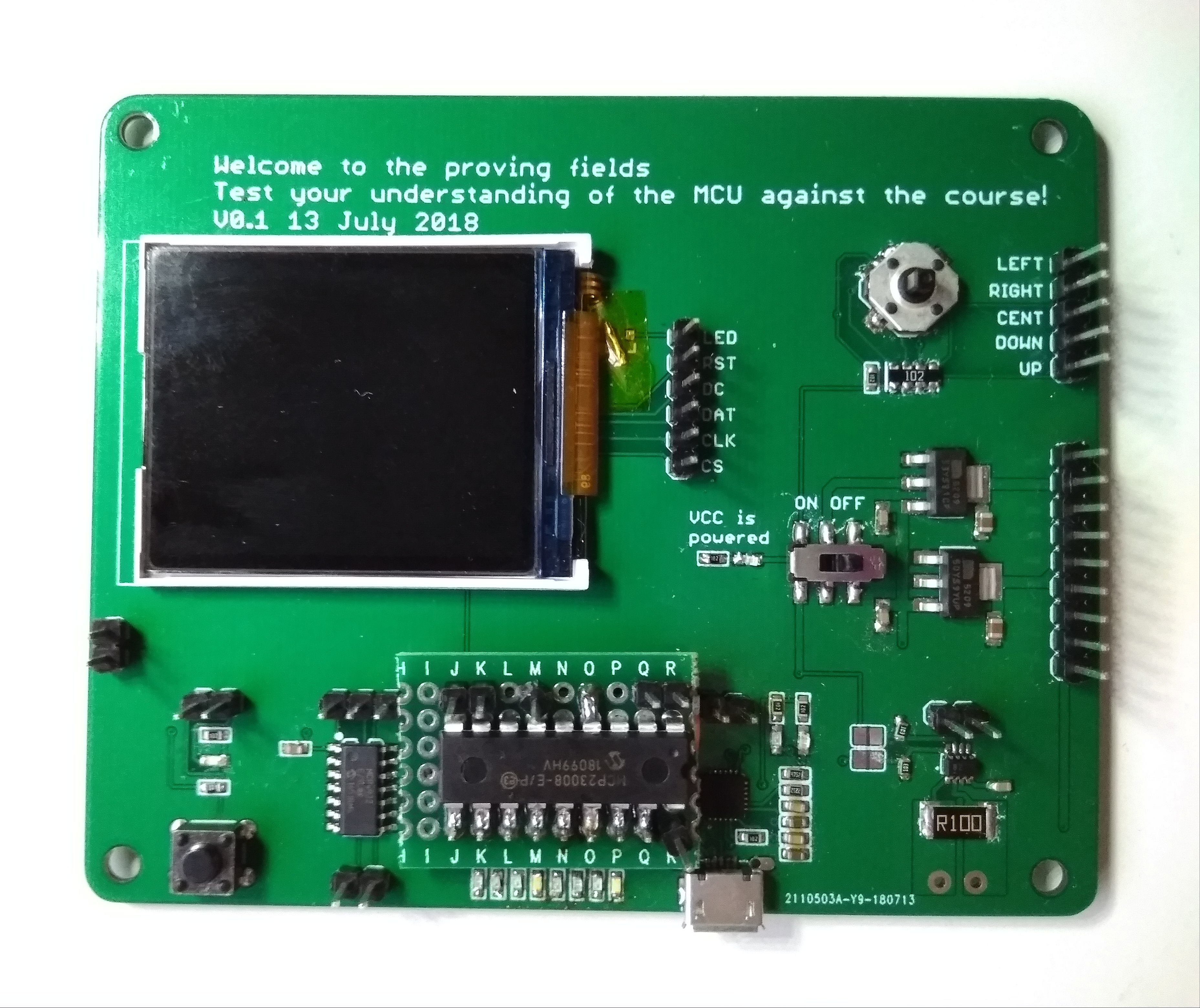
This board sports the following features:
- Blink an LED (pin toggling)
- Button press (read pin)
- 5 Way Tactile Button (interrupts)
- TFT LCD/DAC, MCP4922 (SPI)
- I/O Expander, MCP23008 (I2C)
- CP2102N UART-to-USB (UART)
- TFT LCD (SPI)
- Current Sensing (I2C)
- Power supply (3.3V and 5V)
The SPI and I2C chips were chosen because they are relatively simple to control and output directly measurable signal. In the case of the MCP23008, it resets to the default state of all GPIO inputs, so if a high output was configured over I2C, this would clearly show up on a measurement. For the DAC, setting a voltage halfway between 3.3V and 0V would clearly demonstrate control over SPI.
The TFT LCD and the current sensing are both useful components, but they also provide an additional challenge beyond simple pin toggling. Finally, a power supply circuit is also provided as an additional option to power the board. It provides both 3.3V and 5V. A USB can be connected to the board, and the USB and V pins can be connected to supply power to the voltage regulators. Note that the VCC line should not be connected to avoid bus contention.
Final Assembled Product
Quickstart
To get you started quickly, I am providing the following code as reference. The code was tested using an ATMEL SAMD21 Xplained Pro. The code provided for the Quickstart guide uses the Atmel Software Framework (ASF) in Atmel Studio. It is assumed that the user has had some familiarity with using ASF, or if not, a new project should be created, and in the ASF Wizard, the appropriate modules should be added.
MCP23008, GPIO Expander (I2C Master, polled)
The following code uses PA05 as the reset toggle pin, PA08 as the SDA, and PA09 as SCL. SERCOM2 is used for I2C. This code will turn GP0 into an output pin and set it to high, demonstrating that I2C communication with the MCP23008 is working.If the toggle pin is not required, then it should be tied to high.
#include <asf.h>

#define DATA_LENGTH 2

#define OLAT 0x0A // output latch
#define IODIR 0x00 // direction of data I/O
#define GPIO 0x09 // Read current state of each pin

static uint8_t my_buffer[2] = {IODIR, 0xFE};

static uint8_t read_buffer[DATA_LENGTH];

#define SLAVE_ADDRESS 0x27

#define TIMEOUT 1000

struct i2c_master_module i2c_master_instance;

void configure_i2c_master(void);
void reset_slave(void);
void mcp23008_setup(struct i2c_master_packet packet);

void configure_i2c_master(void)
{

	struct port_config pin_conf;
	port_get_config_defaults(&pin_conf);

	/* Configure LEDs as outputs, turn them off */
	pin_conf.direction  = PORT_PIN_DIR_OUTPUT;
	port_pin_set_config(PIN_PA05, &pin_conf);
	port_pin_set_output_level(PIN_PA05, true);


	struct i2c_master_config config_i2c_master;
	i2c_master_get_config_defaults(&config_i2c_master);

	config_i2c_master.buffer_timeout = 10000;
	config_i2c_master.baud_rate = I2C_MASTER_BAUD_RATE_400KHZ; // at 3.3V, the default i2c baud rate for the MCP23008 is 400kHz

	i2c_master_init(&i2c_master_instance, SERCOM2, &config_i2c_master);

	i2c_master_enable(&i2c_master_instance);
}


void reset_slave(void){
	port_pin_set_output_level(PIN_PA05, false);
	delay_ms(1);
	port_pin_set_output_level(PIN_PA05, true);
}

void mcp23008_setup(struct i2c_master_packet packet){
	reset_slave();
	static uint8_t temp[2];
	temp[0] = IODIR; // direction of pin
	temp[1] =  0xFE; // last pin output, all input
	packet.data = temp;
	i2c_master_write_packet_wait(&i2c_master_instance, &packet);
	temp[0] = OLAT; // output latch
	temp[1] = 0x01; // last pin high
	packet.data = temp;
	i2c_master_write_packet_wait(&i2c_master_instance, &packet);
}

int main (void)
{
	system_init();
	delay_init();


	configure_i2c_master();

	uint16_t timeout = 0;

	struct i2c_master_packet packet = {
		.address     = SLAVE_ADDRESS,
		.data_length = 2,
		.data        = my_buffer,
		.ten_bit_address = false,
		.high_speed      = false,
		.hs_master_code  = 0x0,
	};

	mcp23008_setup(packet);

	while (1) {
		/* Is button pressed? */
		if (port_pin_get_input_level(BUTTON_0_PIN) == BUTTON_0_ACTIVE) {
			/* Yes, so turn LED on. */
			port_pin_set_output_level(LED_0_PIN, LED_0_ACTIVE);

		} else {
			/* No, so turn LED off. */
			port_pin_set_output_level(LED_0_PIN, !LED_0_ACTIVE);
		}
	}
}
MCP4922, Digital to Analog Chip (DAC) (SPI master, polled)
I used the ASF Reference for the SPI pinmux configuration. This code uses PA04 as MOSI, PA05 as SCK and PA17 as the CS. You can use any pin as the Chip Select (CS)/Slave Select (SS).
This code sets an arbitary output on channel A other than zero which can be observed using a multimeter.
#include <asf.h>

// ***** spi ***** //

// SPI uses SERCOM0
// Configuration A
// 0 MOSI : PA04
// 1 SCK  : PA05
// 3 SS   : PA17


#define BUF_LENGTH 2


struct spi_module spi_master_instance;
struct spi_slave_inst slave;

static uint8_t buffer[BUF_LENGTH] = {
	0xFC, 0xF0
};

void configure_spi_master(void)
{
	struct spi_config config_spi_master;
	struct spi_slave_inst_config slave_dev_config;
	/* Configure and initialize software device instance of peripheral slave */
	spi_slave_inst_get_config_defaults(&slave_dev_config);
	slave_dev_config.ss_pin = PIN_PA17;
	spi_attach_slave(&slave, &slave_dev_config);
	/* Configure, initialize and enable SERCOM SPI module */
	spi_get_config_defaults(&config_spi_master);
	config_spi_master.mux_setting = SPI_SIGNAL_MUX_SETTING_A;
	config_spi_master.pinmux_pad0 = PINMUX_PA04D_SERCOM0_PAD0;
	config_spi_master.pinmux_pad1 = PINMUX_PA05D_SERCOM0_PAD1;
	config_spi_master.pinmux_pad2 = PINMUX_UNUSED;
	config_spi_master.pinmux_pad3 = PINMUX_UNUSED;
	//config_spi_master.mode_specific.master.baudrate = 3000000;
	spi_init(&spi_master_instance, SERCOM0, &config_spi_master);
	spi_enable(&spi_master_instance);
}

void set_output(uint8_t pin, uint16_t value){
	static uint8_t temp[2];
	if (pin==1){
		temp[0]=(0b0011<<4)|(value>>8);
		temp[1]= 0b11111111 & value;
	}
	else {
		temp[0]=(0b1011<<4)|(value>>8);
		temp[1]= 0b11111111 & value;
	}
	spi_select_slave(&spi_master_instance, &slave, true);
	spi_write_buffer_wait(&spi_master_instance,temp,2);
	spi_select_slave(&spi_master_instance, &slave, false);
}

int main (void)
{
	system_init();
	delay_init();

	configure_spi_master();
	set_output(1,160);

	while (1) {
		/* Is button pressed? */
		if (port_pin_get_input_level(BUTTON_0_PIN) == BUTTON_0_ACTIVE) {
			/* Yes, so turn LED on. */
			port_pin_set_output_level(LED_0_PIN, LED_0_ACTIVE);
			set_output(1,160);

		} else {
			/* No, so turn LED off. */
			port_pin_set_output_level(LED_0_PIN, !LED_0_ACTIVE);
		}
	}
}
TFT LCD, ST7735, SPI
Getting the LCD to work can be a little annoying, so some work derived from Adafruit's fine ST7735 library is used to get the screen to work.
A short explanation is that this screen uses the SPI module to send information
The file is a little too big so this is a link to the Github page that contains code for the LCD. Provided here is some starter code that turns the screen red when you press the button on the Xplained board. The ASF modules of SPI (Polled), and Delay have to be added before the code can be compiled.
If the delay is not working, check that delay_init() was added. For the SAMD10, the internal 8Mhz oscillator was used to drive the 48Mhz Digital Frequency Locked Loop (DFLL), which is configured in conf_clocks.h. Check that CONF_CLOCK_FLASH_WAIT_STATES is set to 1.
For the SAMD21 Board
MOSI: PA4, SCK: PA5, DC: PA16, CS: PA17, RST: 3.3V, LED: GND.
For the SAMD10 Board
MOSI: PA22, SCK: PA23, DC/AO: PA16, CS: PA17, RST: 3.3V, LED: GND
#include <asf.h>
#include "lcd.h"

int main (void)
{
	system_init();
	delay_init();
	configure_port_pins();

	LCD_init();
	LCD_clearScreen(BLACK);

	while (1) {

		if (port_pin_get_input_level(BUTTON_0_PIN) == BUTTON_0_ACTIVE) {

			port_pin_set_output_level(LED_0_PIN, LED_0_ACTIVE);

			LCD_clearScreen(RED);
		} else {

			port_pin_set_output_level(LED_0_PIN, !LED_0_ACTIVE);
		}
	}
}
5 Way Tactile button, interrupts
I thought that having the screen change colour would be a pretty striking indication that the device is working. When you press the button, the screen turns red. It uses PB11 as the trigger pin.
#include <asf.h>
#include "lcd.h"

void extint_detection_callback(void)
{
	LCD_clearScreen(RED);
}

void configure_extint_channel(void)
{
	struct extint_chan_conf config_extint_chan;
	extint_chan_get_config_defaults(&config_extint_chan);
	config_extint_chan.gpio_pin = PIN_PB11A_EIC_EXTINT11;
	config_extint_chan.gpio_pin_mux = MUX_PB11A_EIC_EXTINT11;
	config_extint_chan.gpio_pin_pull = EXTINT_PULL_UP;
	config_extint_chan.detection_criteria = EXTINT_DETECT_BOTH;
	extint_chan_set_config(11, &config_extint_chan);

}
void configure_extint_callbacks(void)
{
	extint_register_callback(extint_detection_callback,
	11,
	EXTINT_CALLBACK_TYPE_DETECT);
	extint_chan_enable_callback(11,
	EXTINT_CALLBACK_TYPE_DETECT);
}


int main (void)
{
	system_init();
	configure_extint_channel();
	configure_extint_callbacks();
	delay_init();
	configure_port_pins();

	LCD_init();
	LCD_clearScreen(BLACK);

	while (1) {
		if (port_pin_get_input_level(BUTTON_0_PIN) == BUTTON_0_ACTIVE) {
			port_pin_set_output_level(LED_0_PIN, LED_0_ACTIVE);

		} else {
			port_pin_set_output_level(LED_0_PIN, !LED_0_ACTIVE);
		}
	}
}
UART
Implementation of UART was done with a CP2012N chip.
Future Work
I did not include a potentiometer this time to test the ADC because of a lack of space. Improvements include adding a 'tester' microcontroller which might give particular challenges on the LCD that might spice up testing a little. 10k pullups will also be useful on the I2C lines.
The placement of the 5 way button can certainly be improved so that it is in a area that is easier to access.