Just pile it on (More LEDs) (12)

It starts to get messy if you want to add more than 3 LEDs to your project because each LED requires a pin. While there are one wire protocols that make this a much simpiler task, what if you really really wanted LEDs in your project?
Well one solution would be to use external logic to solve this problem, much like how 1 wire protocols work, but in this case, we will be using three wires to control 8 LEDs.
Binary Crash Course
Computers work by using digital logic. That means that they only recognize two numbers, 0 and 1, or low and high. That is because computers can only read voltage levels. We can't use numbers in between 0 and 1 because there is an infinite number of them, and drawing the line would be very difficult. However, just by basing our logic on 0 or 1, we can represent almost anything.
Imagine you only had a binary digit. That means that you can only represent 0 and 1. In this world, you can only count up to 1. It is either nothing 0, or 1. We don't start with 1 because then we won't have space to say that there's nothing there.
Now we add a digit. We have two separate items that can go from 0 to 1 or vice versa. Because numbers are unique, how many unique combinations can be create?
It turns out that there are four 'numbers': 00, 01, 10, 11. These correspond to 0, 1, 2, 3 respectively. Notice how if we add 1 to 01, it 'carries over' to the next digit? This is also known as base 2 counting. You are probably familiar with base 10, or decimal counting, which carries over when the number reaches 10 to the next digit. As in base 10, we start from the right. You can also imagine the numbers to be 'pushing' each other to the left. If a 1 comes in, and there is a 0, then it can say, else, the 1 that's already there is pushed to the next digit
So now for a little test, can you write down the next number to 101 in binary? What does this number correspond to?
Did you get 111 and 7? Great! Now you can start counting in binary!
Our 595 chip
There are two ways which we can do this, and the more popular means is through using a shift register, also known as 54HC595.
The pins of this chip are labeled as follows:
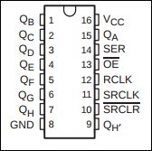
And what these pins do are:
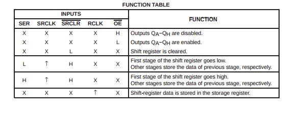
These images are sourced from the manufacturer's datasheet. By examining the datasheet, you should be able to determine how each chip works. In our case, we know that Q is the outputs, and we want them enabled. This means that we have to set the pin OE to low, ie 0V.
Now we have up arrows in the columns SRCLK and RCLK. This means that upon change from low to high, the function will be enabled. We will usually send regular pulses to CLK pins, so they trigger periodically. In our case we want the shift register data to be stored and our shift register to respond, so we will send clock pulses to these pins.
SRCLR clears the shift register when low, so that means that in normal operation, we want it to be high, ie, not clearing the shift register.
So all we are left with is SER. When low, the first stage of the shift register goes low, when high, the first stage goes high.
Putting it all together, SER is where we send data in by, SRCLK is our clock pin, and RCLK is our latch pin. Our clock pin helps us to count the bits, so for example, we set our serial HIGH, and let SRCLK count:
- At count 1, Stage 1 is HIGH (0001)
- At count 2, Move Stage 1 to Stage 2, Stage 1 is HIGH (0011)
- (set SER LOW), At count 3, Move Stage 2 to Stage 3, Move Stage 1 to Stage 2, Stage 1 is LOW (0110)
It is simply like counting in binary! Plus now you know how to read a datasheet! Just a final note, when latch is low the chip is reading the data. When it goes from low to high the chip sends this data to its output pins, so you won't see flickering as we shift the numbers in place.
Very fortunately for us, Arduino already has this functionality built in so we won't have to program the timing ourselves. This function is known as shiftOut. It takes four values, the data pin, the clock pin, the order of bits, and the value to shift out. As we now know, the data pin is our SER, and the clock pin is our SRCLK.
The order of bits is a little tricky. It goes as either MSBFIRST (Most Significant Bit First) or LSBFIRST (Least Significant Bit First. MSBFIRST means if Stage 8 is high, the first value that goes in is high and it gets pushed to the left (1000 0000). LSBFIRST means that if Stage 8 is high, only at count 8 do we set the data pin/SER to be high (0000 0001).
So the code will be:
shiftOut(2,3,MSBFIRST,8)
Now all you have to do is to is to connect the 595 chip to the microcontroller and you're ready to go!
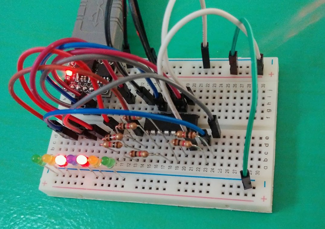
Figure 1. Shift Register with Digispark
As you realize, having many LEDs requires many resistors. One easy and neat way to do this is to use a through-hole resistor array. They provide resistors in parallel in a breadboard format and they all connect to a single pin (ie a single bus), which you can then tie to ground or 5V. They can be found at Digikey or Arrow.
What you learned
- How to read and use binary.
- How to use a 545 shift register.
- How to read a datasheet.
- How to use
shiftOut.