IKEA TRÅDFRI On/Off Switch Teardown
A look inside IKEA's wireless TRADFRI On/Off Dimmer Switch! This really is a masterclass in designing a wireless button by IKEA.

Tldr; well-designed button with multiple interesting design features. If exposed, well-labelled, debugging pins excite you, you've come to the right place.
I am a big fan of IKEA products.
I'm also a big fan of checking out the electronics of low-cost products.
So when I saw this smart LED bulb and wireless button bundle during my quarterly sojourn to IKEA, I simply could not resist the temptation to open it up and see what IKEA has decided to use for their Home Smart™ products.
Curiously enough, while this bundle was \$14.90 (a bit on the expensive side!). IKEA currently sells a LED bulb for \$19.90, and a button for \$9.90. Another surprising detail is that Zigbee buttons from Chinese retailers also cost about \$15+, making this bundle (button+LED) cheaper than what you can buy elsewhere.
Mechanical
Back
The switch is opened by first unscrewing the back cover.
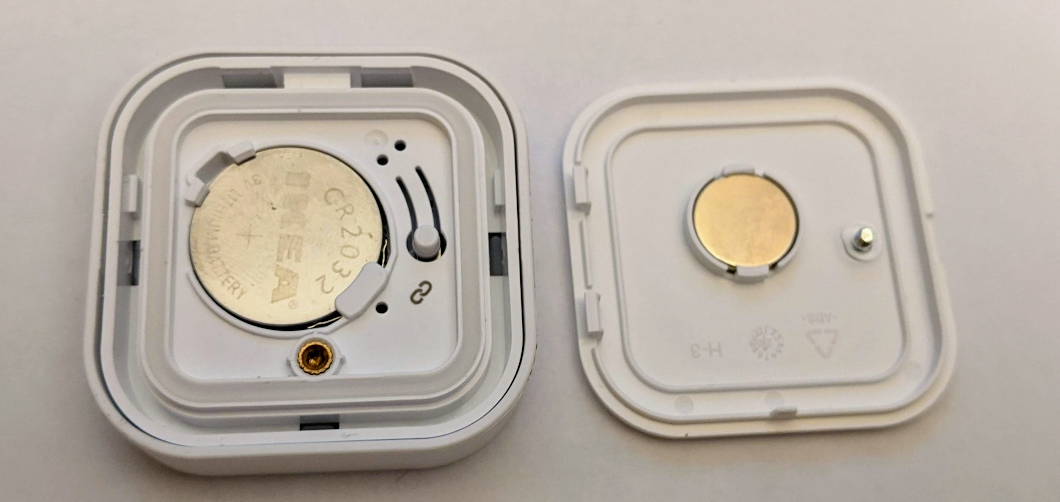
The back cover is held in place by two hinges and a screw. It features a strong magnet in a snap-fit holder to allow the switch to be magnetically attached to surfaces. Not pictured here is a metal plate that IKEA has provided in the box that you can attach to a surface with a screw or sticky tape.
The screw itself features a piece of plastic to prevent it from falling out and getting lost. This is a clever feature I've seen in a few places. Since the plastic spins with the screw, it always remains in the same relative position, and so keeps the screw in the hole.
With regards to using a screw to attach the back cover, although IKEA could have just used a snap-fit feature, however because the battery and pairing button inside the button have to be accessed occasionally, a snap fit feature might be broken as they are not designed for the repetitive stress of opening and reclosing the back cover.
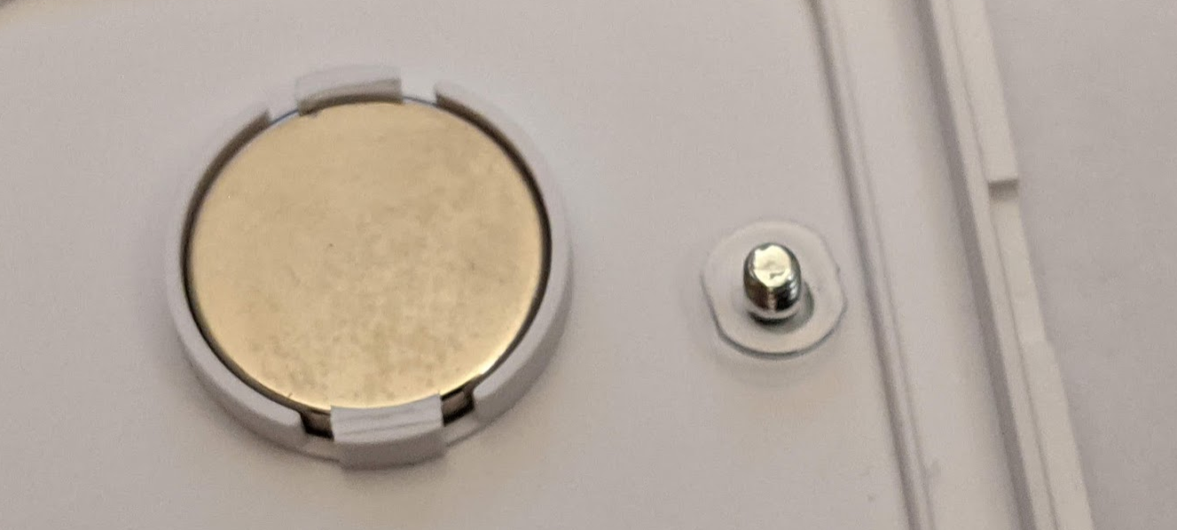
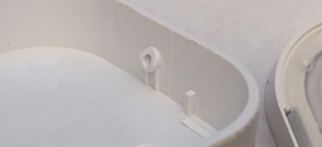
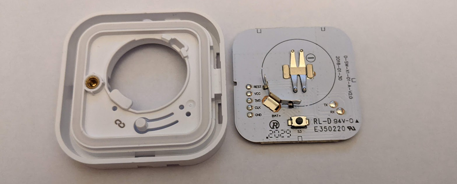
There is a corresponding knurled insert that the screw attaches to. Two points about this design:
- Using an insert instead of using a self-threading screw and empty post improves the durability of the screw hole.
- The insert is fitted into a cylinder with a short boss. This improves reliability because during installation, the insert is heated up to melt the plastic around it to ensure a strong bond. However, this might warp the surrounding plastic. By having a raised cylinder and a boss, this increases the strength of the hole, minimizing warping.
For such a simple attachment mechanism, IKEA certainly has put in a lot of thought and money into ensuring it's durability and reliability.
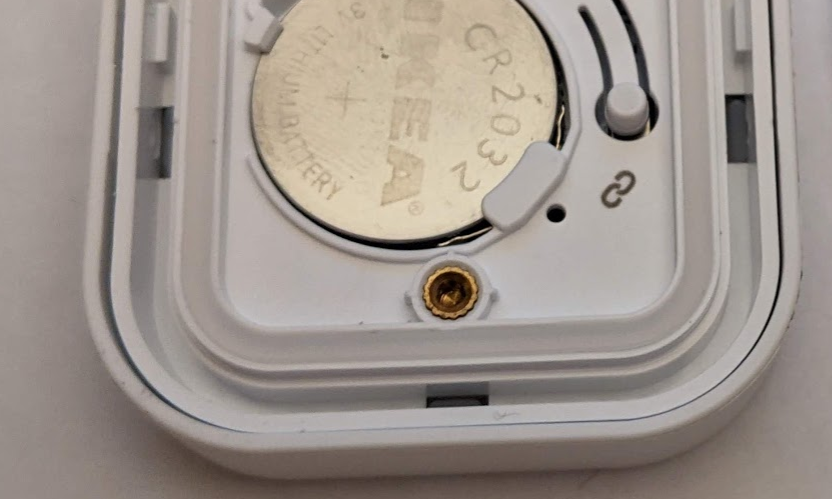
The battery is held in place with a snap fit mechanism, and a convenient hole for a screwdriver to lever out the battery when it is time to be replaced. Again, note that the levering area is reinforced and raised to improve the leverage of the screwdriver. Without this reinforcement, I think it will still work, but it might cause the plastic to flex or break if this is done often.
The whole area is encircled by a translucent silicon O-ring that helps to prevent mositure from getting to the electronics. While this button is not rated for splashes and is only meant to be used inside, I appreciate the attention to detail and potential mishaps.
Front
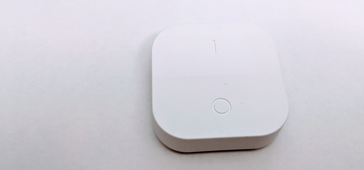
The top of the case features a rocker-style switch, with each portion textured differently to allow you to recognize which side you are pressing by feel alone.
The front cover is removed by wedging in a flat head screwdriver in the space between the case and top cover, close to the center of the rocker and levering off the top.
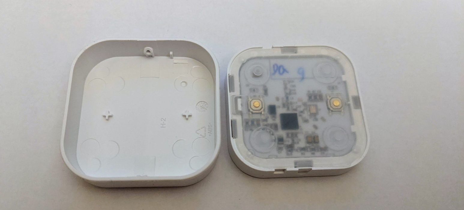
The cover features a two small bosses that enable accurate triggering of the SMD buttons (the gold circles). This is a very common feature for buttons. It also reveals a very interesting design feature. The hinge is not only used for the rocker-style operation, but it also combines a snap fit feature that allows it to be snapped on easily.
Notice how the shaft for the hinge is chamfered so that it guides its way into its corresponding hole.
The PCB itself is covered by a layer of silicone that is taped down by double-sided tape all around its edges. This helps in keeping the moisture away from the PCB, and provides a nice smooshy feeling when triggering the button.
The PCB is held in place by two locking pieces of plastic and a snap-fit hinge. You can see that there is an empty channel around the snap-fit hinge that allows it to rock back and forth. Another feature that we can observe more closely here is the guide posts at all four corners used to guide the silicone into position.
Another wonderful bit of design is the cantilevered button smoosher that provides easier access to the S3 button which is used for commissioning lights instead of a paperclip hole that most devices cheerfully provide, assuming that a. You have sharp, narrow, pointy object at hand. b. It is easy to hold down. Again, 10 points to IKEA for design here.
You can see that the case is used to hold the battery in place. This is another important design feature when designing small wireless products. You don't always need (or have the space for!) a dedicated battery holder.
Electronics
ICs
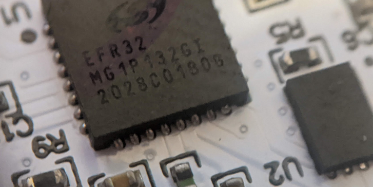
A Silicon labs EFR32MG1 IC runs the show for this button. The markings indicate that it is a 256KB, TX/RX device, and it was manufactured in 2020, on the 28th week (July 6th! Pretty fresh). This is similar to the controller found in an earlier teardown of the IKEA Gateway.
While this particular IC is not recommended for new designs because of newer developments from Silabs, it is supported all the way to 2027 because of the product longevity commitment by Silabs. That is something quite valuable especially if you plan to manufacture a product for a long time to come.
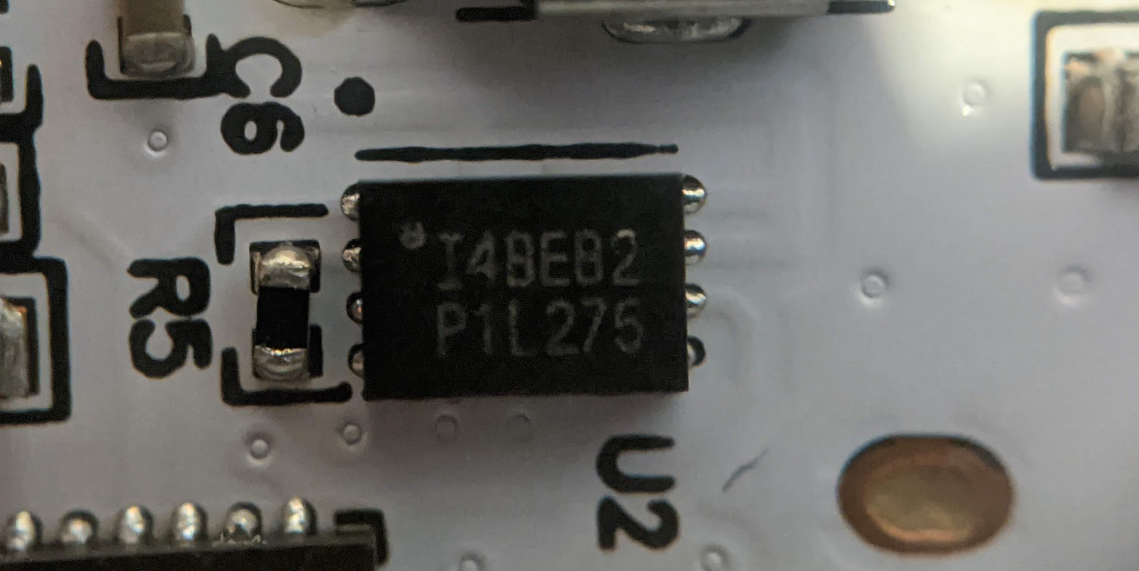
I was not able to identify this chip, but if I had to guess, based on the footprint and the purpose of the PCB, it probably serves as the flash storage for the device.
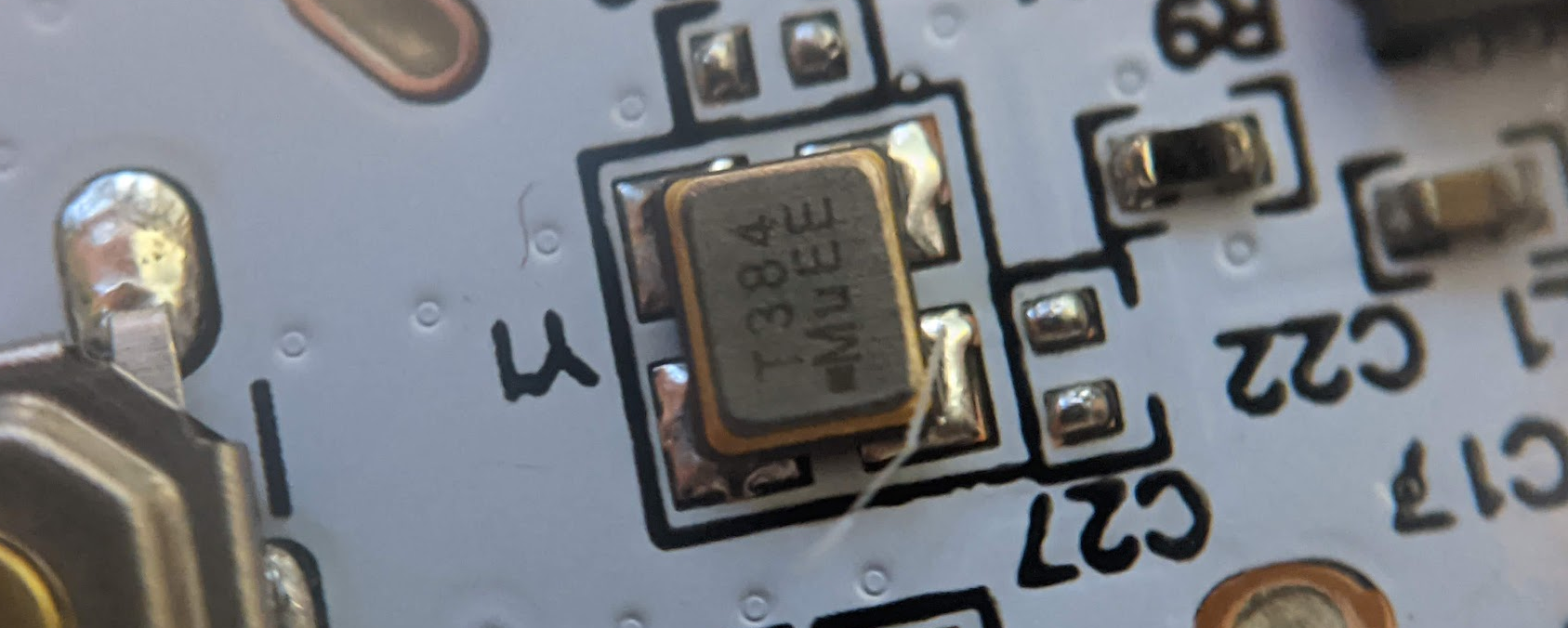
My best guess is that this is the 8Y series of crystals from TXC. M indicates Mhz, u is not known, E is 10ppm (-20 ~ +70 $^{\circ}$) and E is 10ppm (frequency tolerance at 25$^{\circ}$C. This is an IC that has also been seen in other IKEA teardowns.
Board
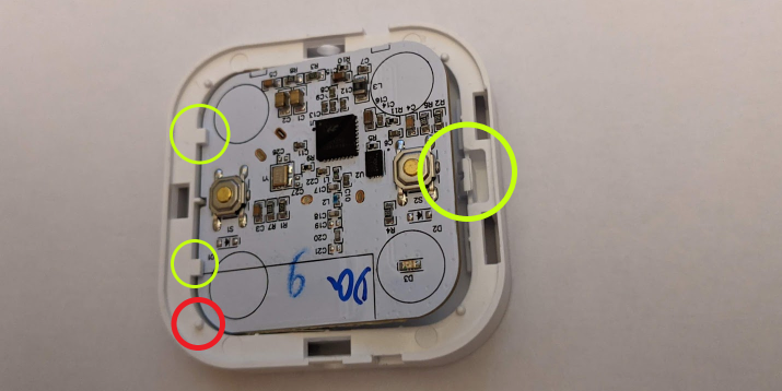
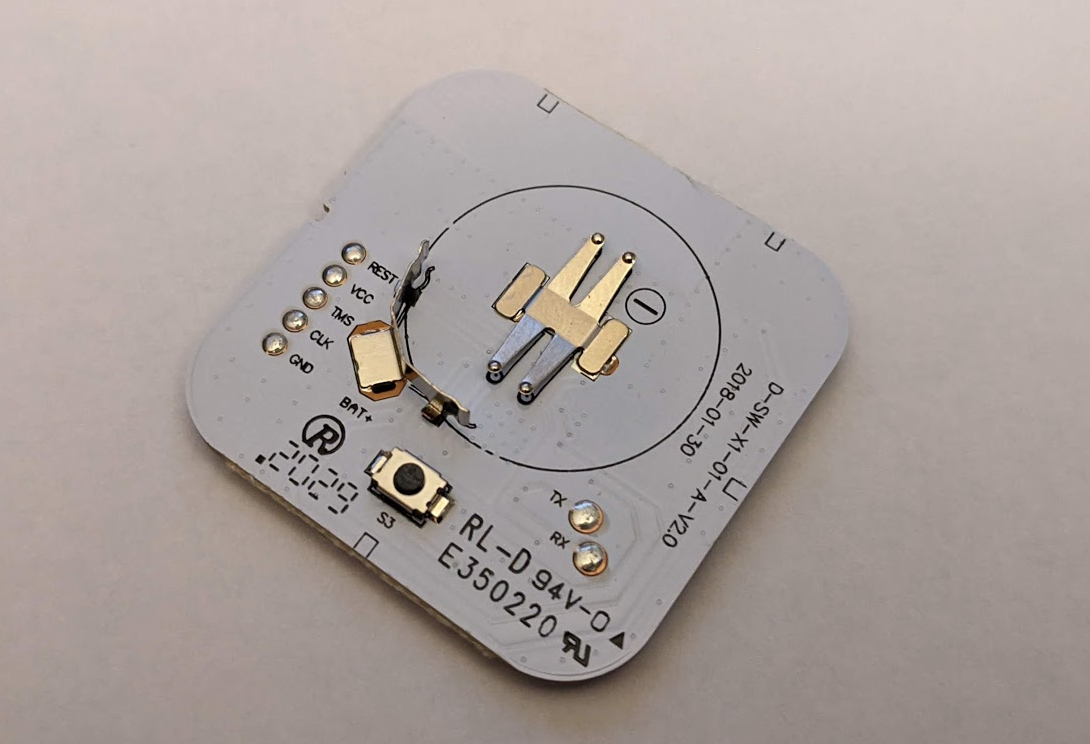
Happily enough the programming pins are exposed. Huzzah! And they are very nicely labeled and laid out for us too.
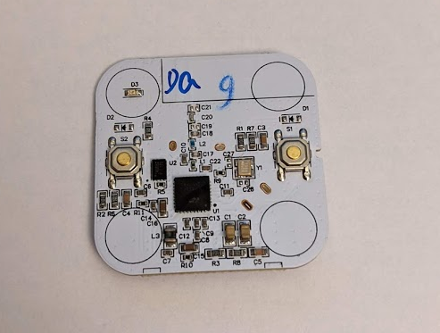
Plenty of surface mount circuitry on the top of the board. Other than the two buttons, we also can see a red LED (D3) at the top corner here. It is used to indicate paring status, although I feel that it should have been mounted on the other side for better visibility because you'd be looking at the back of the button when doing the pairing process. The plastic on the front is too thick for it to be properly visible too.
Notice that diodes D1 and D2 are missing, as well as the capacitor load pins C23 and C26. This indicates to me that this board has gone over a few rounds of testing and it was found that these parts weren't necessary. Rather than making a new board, the team decided to reuse the old board as well as the old solder stencil since these pads have solder on them.
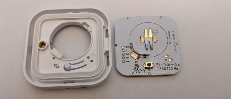
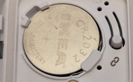
Something really fun that I noticed was that the holes in the back of the case actually line up to the testing pads on TX, RX, and BAT+ (BAT- presumably can be reached when the battery is not inserted). While the programming pins are not exposed, this still allows for some level of debugging over the exposed UART pins.
Firmware
The code runs Zigbee version 3 with the Home Automation profile. It supports Zigbee Touchlink to commission Zigbee nodes that are physically close together. Four quick presses on the pairing button on the back resets the switch, and holding down the pairing button when it is close to another IKEA device links them together. Once the other device responds (either when it is blinking or an status indicator lights up), the button can be released.
It can also be linked to other networks that use Zigbee as a means of communication.
Summary
I really enjoyed this teardown as IKEA has made it quite easy to open up and look at the device.
In summary, what we have here is a Thread/Zigbee capable device that can be debugged directly and easily. It features a UART out, two standard buttons for interaction, a red LED indicator, and a dedicated button for pairing. It is also housed in a nice case that can be easily disassembled for reprogramming, has room to fit one CR2032 battery, and has a magnetic back to allow it to be attached to any metallic surface.
So what does this mean for you? Well, if you are in the market for a nice cheap start to smart lights, I highly recommend this bundle. If you want a easily hackable Zigbee/Thread two-function button, I also recommend taking this apart and seeing what you can do with it.
Liked this teardown? Drop me a message about what worked and what didn't! I'm always happy to get feedback.