IKEA SYMFONISK Sound Remote Teardown
Looking inside the Symfonisk remote from IKEA! It is a simple and logical 3D puzzle that fits together securely.

Another day, another teardown. Today the focus of my prying screwdriver is the Symfonisk Sound Remote from IKEA.
It is quite nice to use. It has a brushed plastic texture that keeps it from becoming a fingerprint magnet. It turns smoothly, and the rubber feet that is used for the base is sticky enough to give the sensation of weight.
What I didn't like was the wobble of the button. It is not noticeable at first if you use a finger to spin the knob, however if you hold the button and wiggle it, there is about 1mm of wobble.
Usage
It operates very similarly to the IKEA On/Off Switch: a pairing button is hidden the battery compartment, and a single CR2032 battery used to power the device. The button offers 4 modes of control: single press, double press, triple press, and turning left or right.
Pairing it with the lightbulb I had allowed me to control the intensity of the light, as well as to turn it off and on. However, I ran into the issue where there was a small delay in the light response when adjusting the brightness. This is understandable as the button is not meant to be always transmitting rotational data, but there were some times where it failed to respond at all.
Mechanical
The top is honestly not very interesting so let's just hop directly to the back.
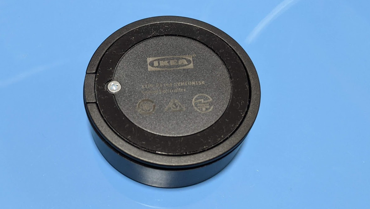
The back is held in place with a standard Philips screw. Using my Adafruit Black™ Screwdriver, I removed it and opened the back cover.
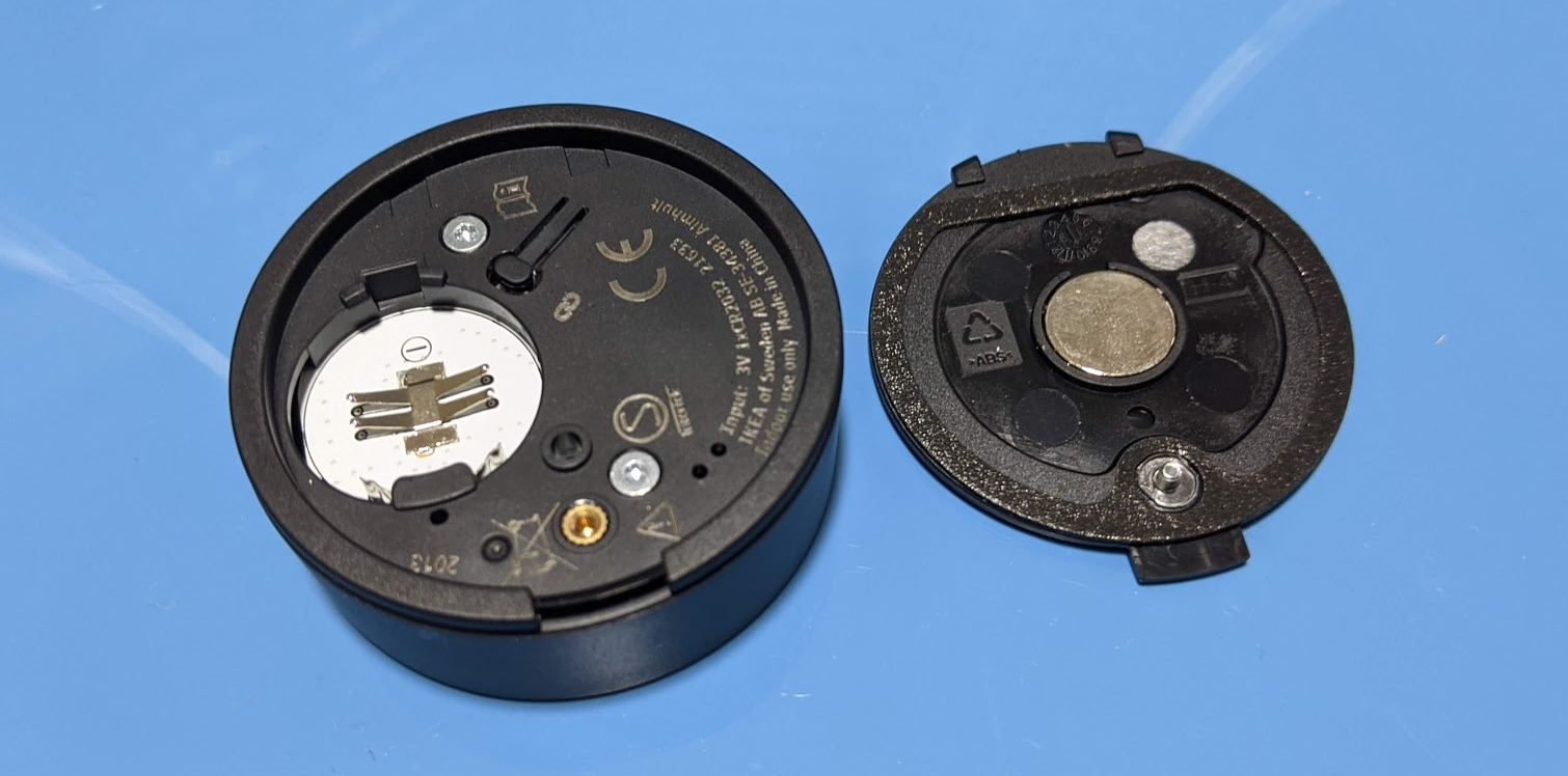
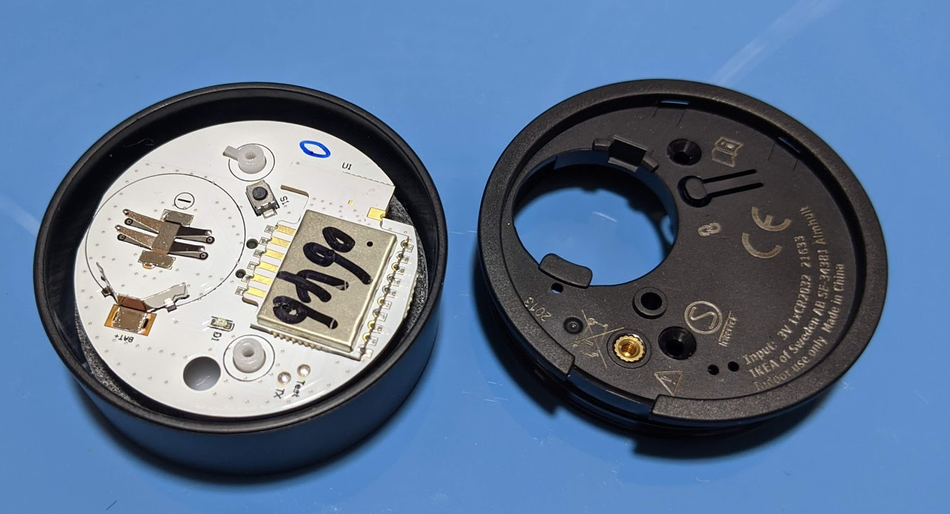
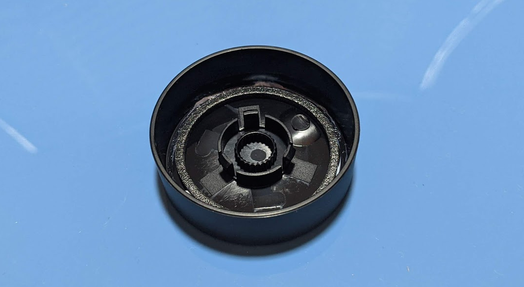
The bottom plate houses the magnet that can be used to attach the button to a magnetic surface. The bottom plate screw is captured by a thin piece of plastic which prevents the screw from falling out and getting lost.
IKEA expects users to open and close the bottom plate often as seen by the brass insert that the bottom plate screw attaches to. In fact, seeing how the cover shares the same mechanism as the On/Off Switch (having a captured screw and a insert) reinforces my initial guess that it was designed this way to facilitate multiple opening/closing operations.
One new addition is the use of Torx star screws instead of regular Philips head screws. They sit flush on the bottom surface thanks to the countersunk holes. The screws are also self-threading, meaning they cut into plastic standoffs below them. I can think of two reasons for this design:
- The Torx star screws are used to indicate that it shouldn't be disassembled further. Most people don't have a Torx screwdriver lying around.
- The Torx screws aren't meant to be regularly opened, so there is no need for an insert, unlike the cover.
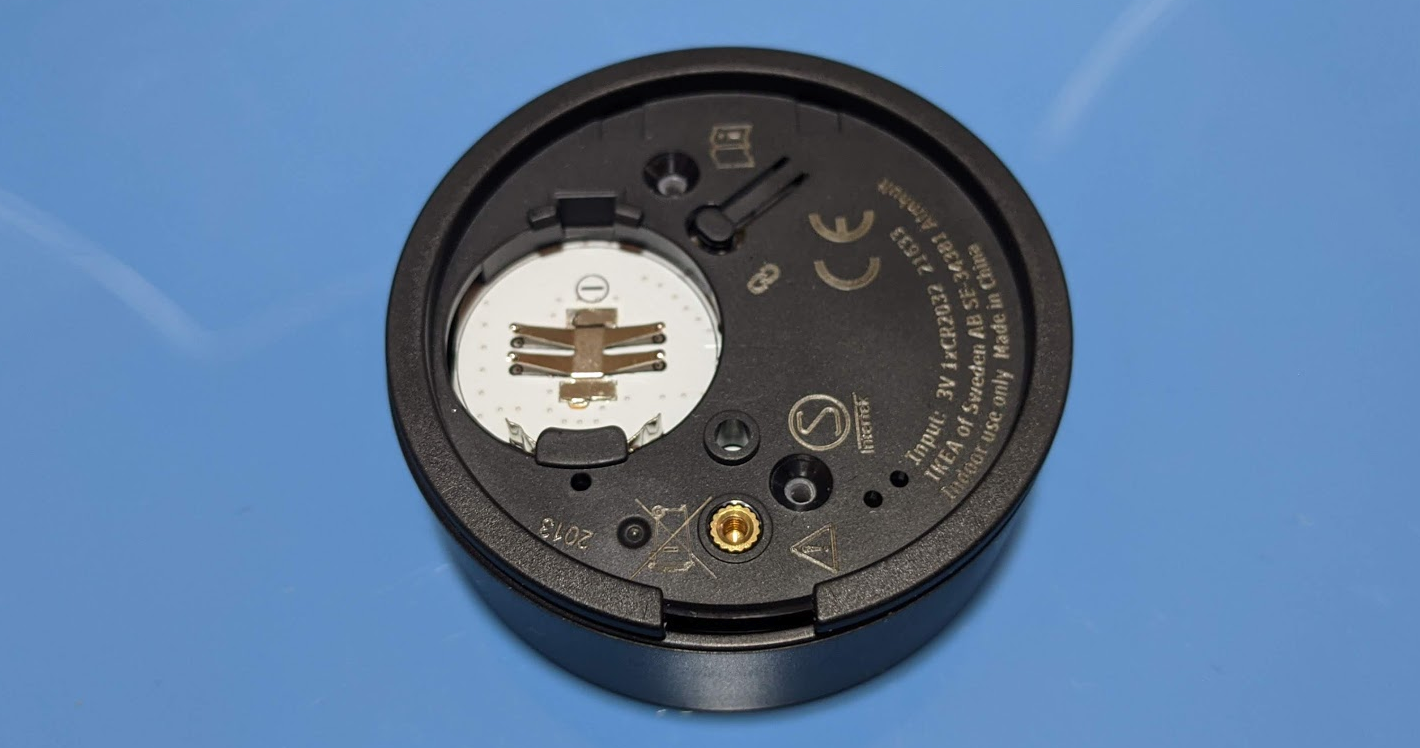
For the battery compartment, there is the repeat of the reinforced edge that is used for levering out the battery once it is dead.
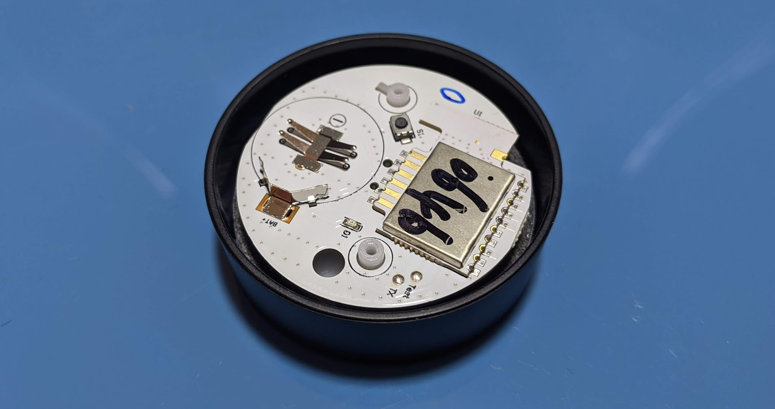
Removing the bottom cover proved to be a little challenging as it is held in place by sticky tape at the rim. We can see the cantilevered arm design used to activate the SMD button below repeated here. The Test and TX pins on the PCB are available through the case, as seen by the two holes near the countersunk hole at the bottom of the picture.
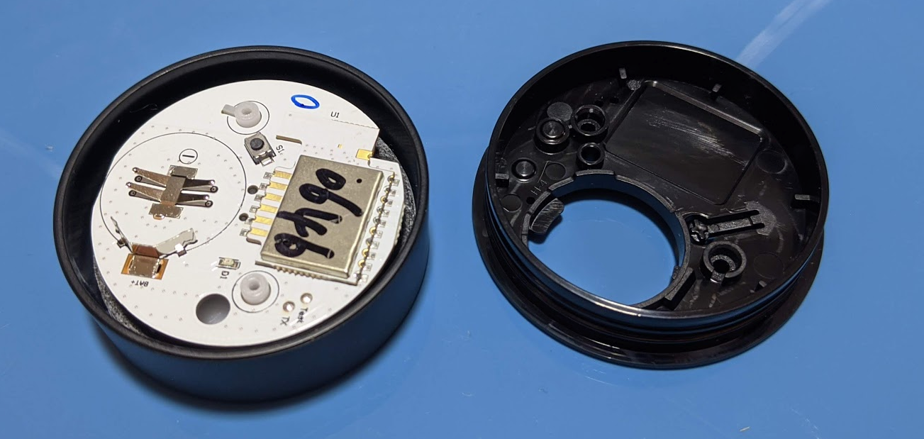
There are ridges on the sides of the bottom cover, and the sticky tape sits on the top rim of the bottom cover. Given these features, I suspect they were designed to prevent water ingress.
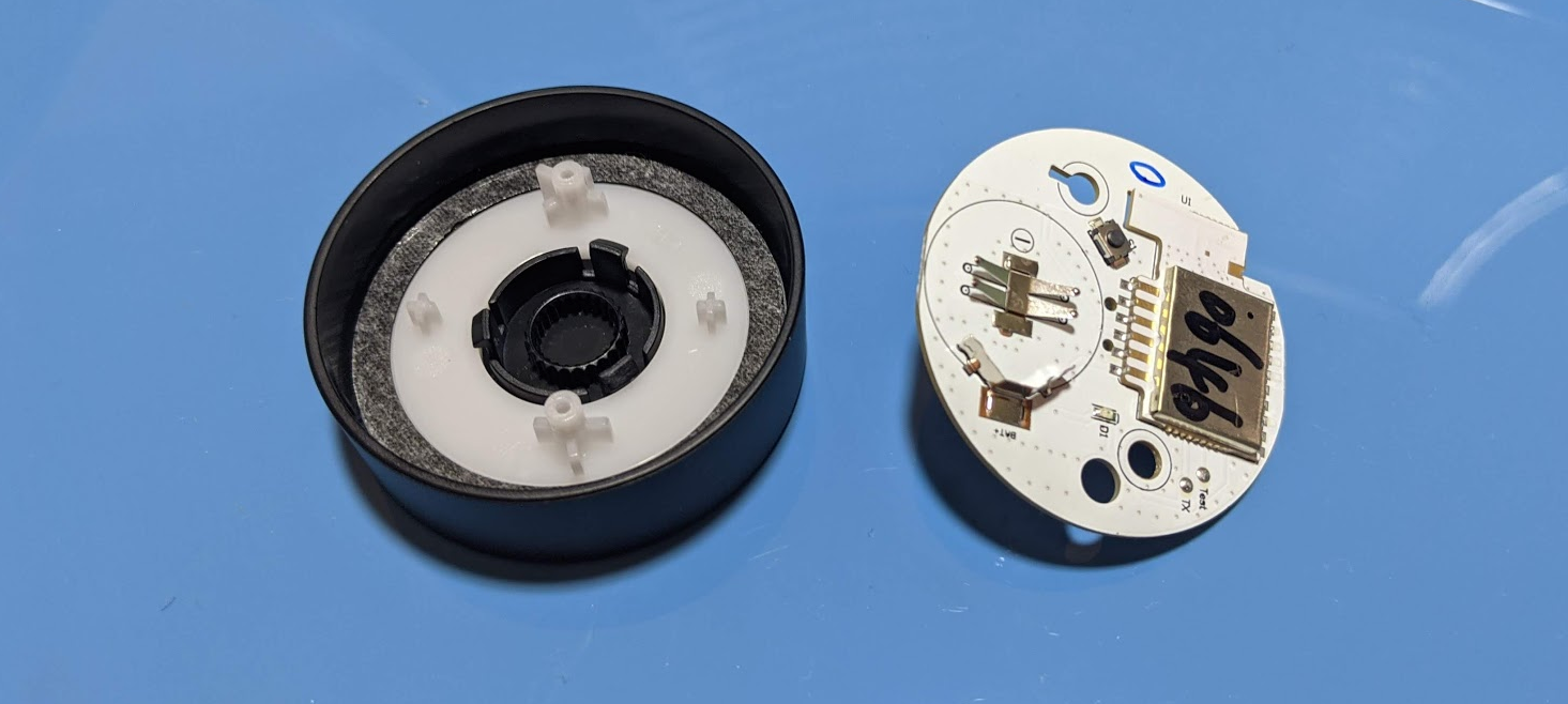
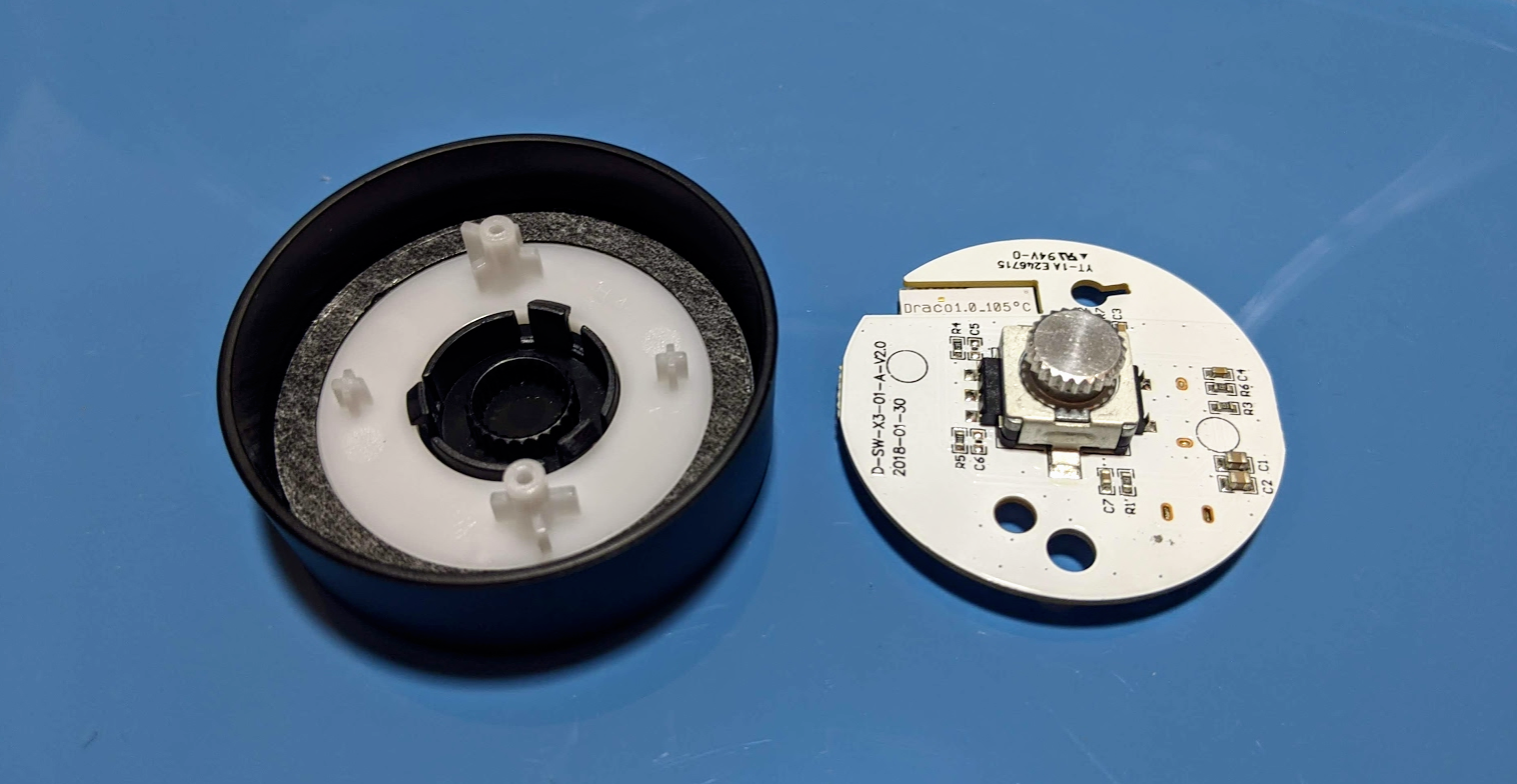
Below the PCB sits a white ABS disk attached to the top cover by a ring of snap-fit attachments.
It fits onto the snap fit ring of the top cover. The two small bosses on the side are meant to provide stability instead of accuracy in triggering buttons. On the underside there is a ring of double-sided sticky tape.
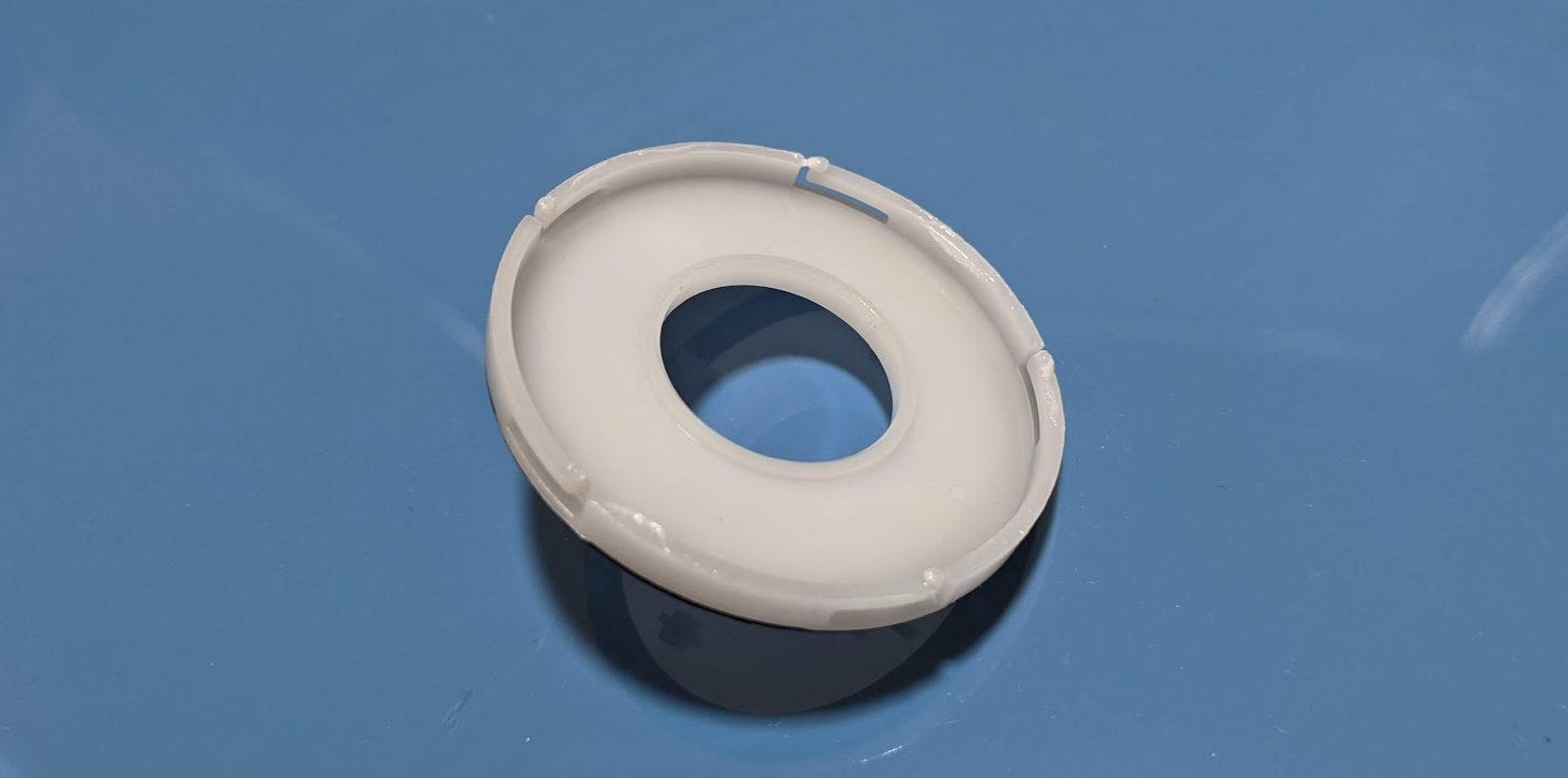
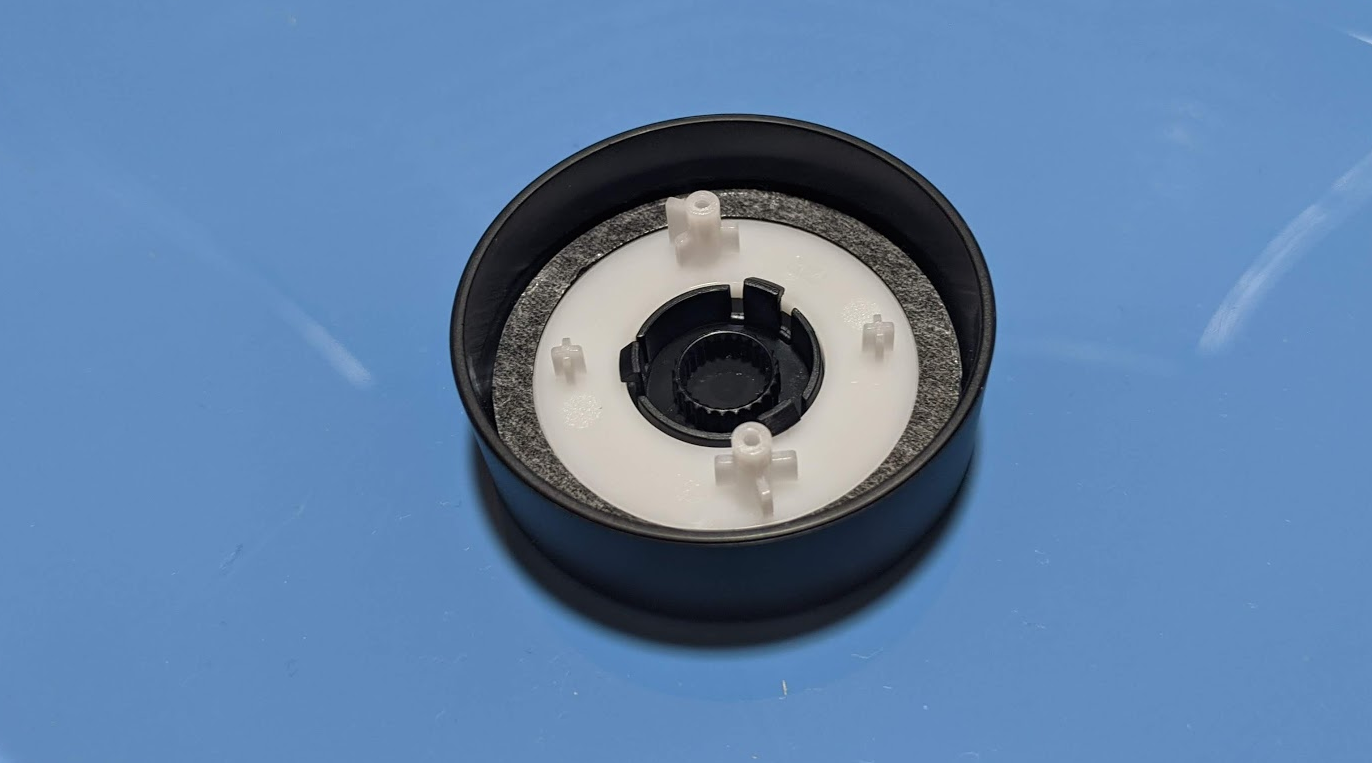
The white ABS disk fits into the top cover and is held in place by the snap-fit holders. Notice how the friction is minimized by the five point knobs. This reduces the amount of area in contact between the two surfaces. These knobs are also positioned on cantilevered arms to allow for some error in manufacturing and assembly.
There is a grease or lubricant on the base of the track, and a foam wall soaked in lubricant forms the other wall. This helps with the smoothness of the rotation. To be honest I was expecting a ball bearing somewhere in the design, given that it would add some heft and and they are not particularly expensive, seeing that you can find them on fidget spinners, and those are a dime a dozen these days.
If we look closely at the design, the entire mechanism is held together by these Torx screws. They attach the white ABS disk to the bottom plate, and sandwich the PCB between them. The top cover is held in place by the snap-fit hinges that fit into the central hole of the white disk.
Electronics
The electronics aren't as interesting as those we found in the On/Off Switch because they are completely encapsulated by the Draco module observed by other people in other IKEA products. No debug out pins here I'm afraid.
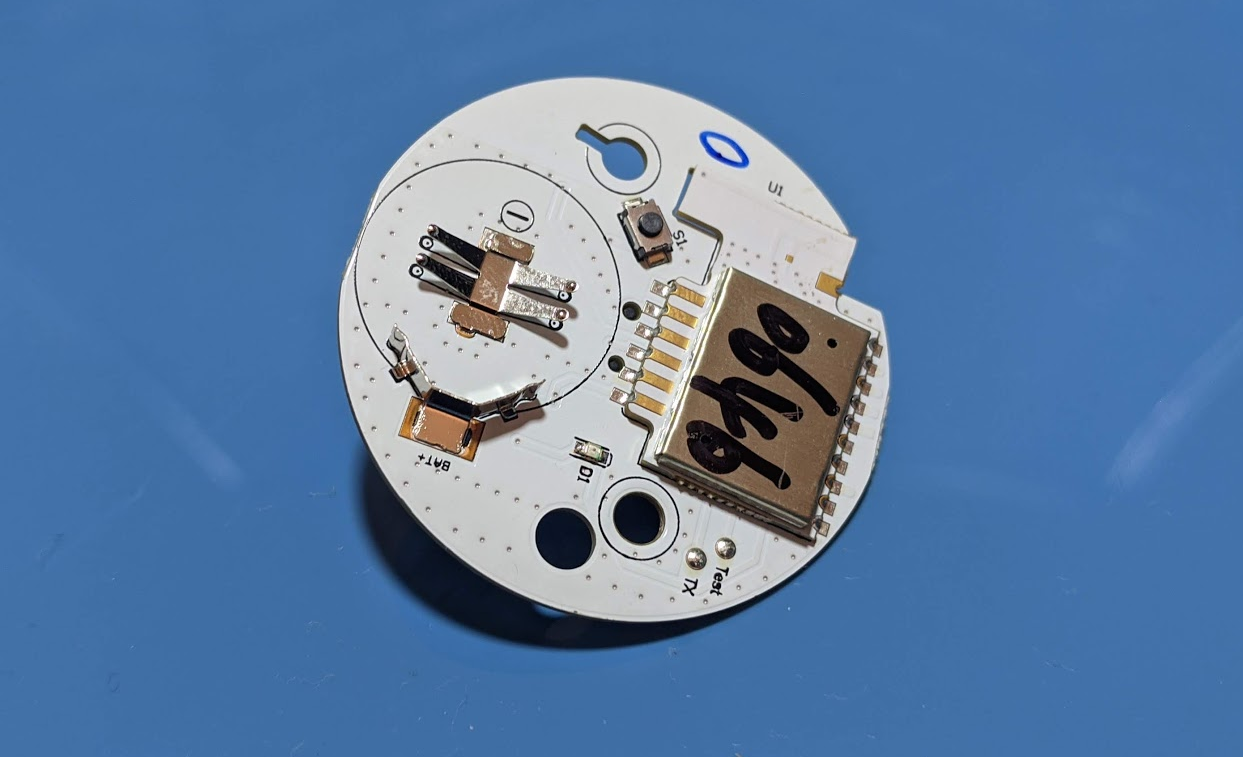
However, it is now easier to solder to more pins, so it's kind of a toss-up really. You are also free to desolder the module to use in other projects if you don't mind the weird shape.
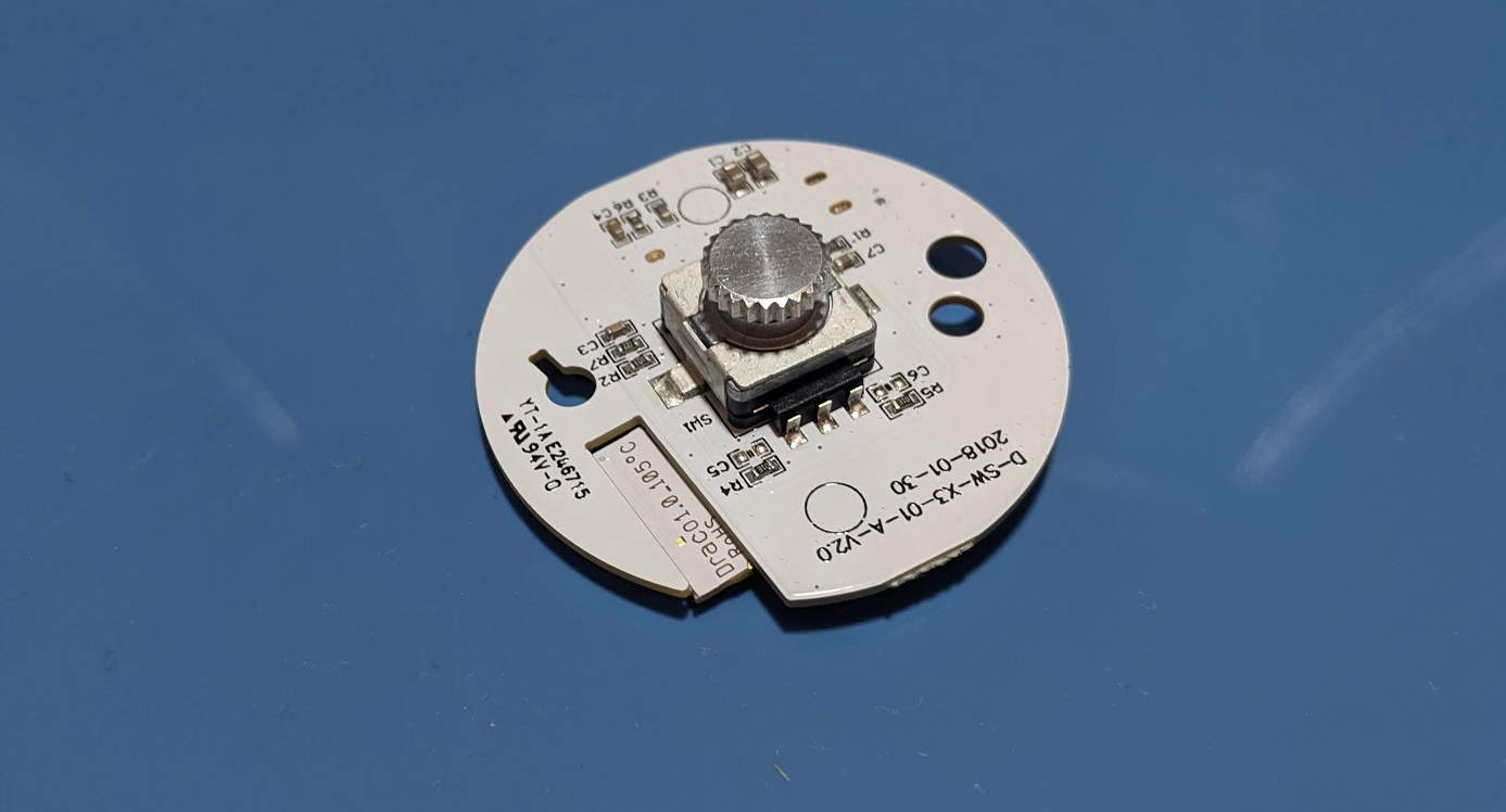
The other side of the board hosts a quadrature encoder that turns smoothly with a some resistance.
Notice the keyway cut into the PCB to help with assembly. It is possible that the two mounting holes are symmetrical, so there might be some ambiguity in positioning the board. With the keyway, this is no longer possible.
The PCB is press-fitted into the corresponding hole on the top cover.
You can clearly see the keyway helping to align the position of the PCB.
Summary
A rather standard design from IKEA, and with some repeated design elements from an earlier teardown. I liked the ingenious way the rotary mechanism was designed, using press fits, snap fits, and screws so that everything fits securely together.