Design Analysis - Table Lamp
A table lamp teardown with a focus on mechanical and electrical design elements.


Lessons Learned
- Locating holes for PCBs and for standoffs
- Using traces to separate positive and negative tracks
- Hinge design with nuts and bolts

This is a lamp that I bought a few years ago for my table. I have not used in awhile and I decided to open it up to take a peek at its innards. Luckily for me, this lamp was held together mostly with screws and tabs, so it was relatively non-destructive to take it apart.
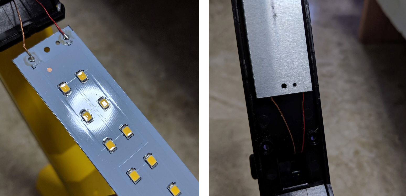
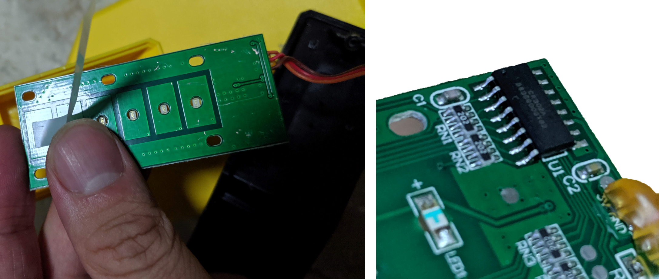
I first removed the cover from the top of the lamp. It is not shown here, but there is a thin slit at the top, presumably for the heat of the LEDs to dissipate. The PCB itself is made of aluminium, which can be a little expensive. With regards to the electronic design, if you take a close look at the image on the left, the 'traces' aren't actually traces. They just separate the positive and negative tracks. This makes for a very low resistance design. There are 18 LEDs in total, and they are arranged in two rows with 3 LEDs in series.
The image on the right shows how the LED panel is mounted. It is basically screwed in with a little locating hole on the right.
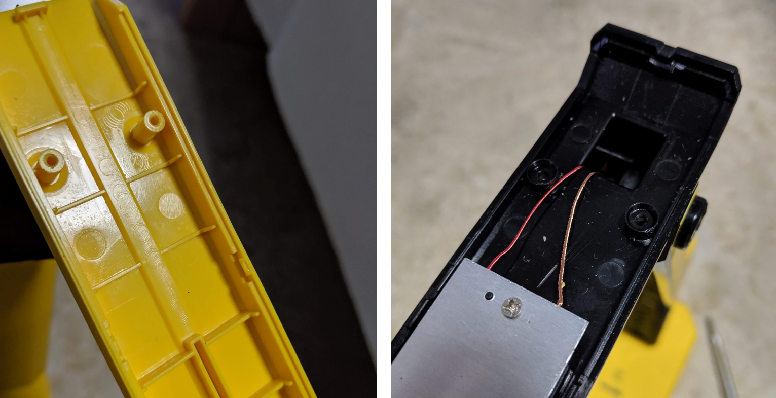
The top case is held in with four screws that thread into the standoffs. Note that there is again a locating ring on the bottom (right picture) for the standoffs. I think this is a pretty clever design.
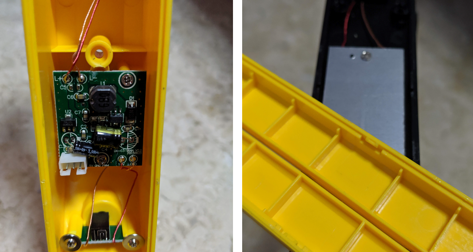
Taking apart the middle section, this is the innards of the device. There is a plug for the touch panel on the front of the middle section. Given that the touch panel on the front commands how bright the LEDs are, and that there is no chip on this main board, my guess is that the three pins are power, ground, and PWM.
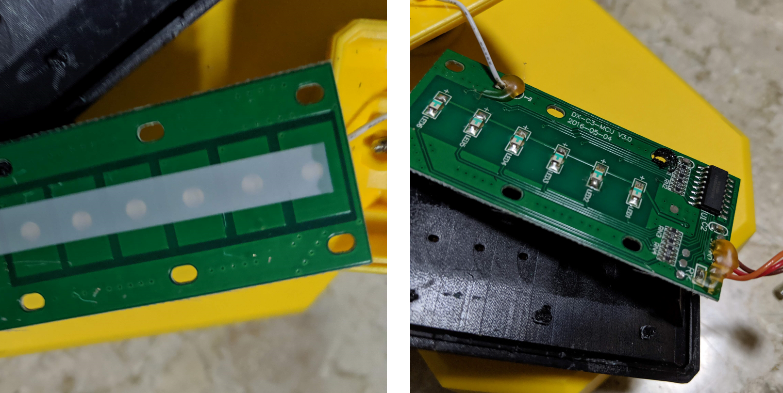
This is the touch panel on the front of the lamp. Nothing too special except that the LEDs are covered with a piece of tape and there are holes drilled into the PCB for the LEDs to be reverse mounted so that they are flush with the PCB. Also note the mounting holes appear to be ABS that have been melted down to hold down the PCB. Note the black stuff on the PCB on the right picture. I suspect these might have been little locators for the PCB, which were then melted to hold the PCB flush to the surface. I had to break these to take out the PCB. Also note the colors of the wire attached to the PCB. Red: power, Brown: ground, Orange: signal (PWM)
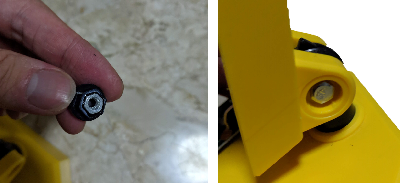
I found the design of the hinge to be quite interesting.It uses a nut and bolt. The nut is epoxied into the cap while the bolt-head is attached to a cap that can be driven by a flathead screwdriver.
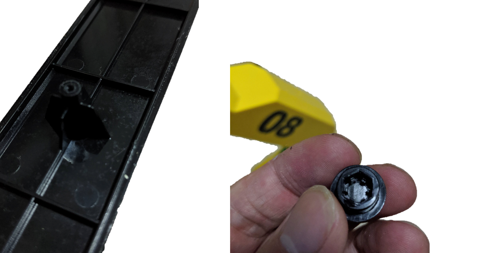
In these last set of two photos is the head of the cap that drives the bolt. By turning this bolt, it pulls the nut in and clamps the joint stiffly, allowing it to stay in position. On the left is another design of a standoff for a screw and it is reinforced with flanges in two axes. In my 3D printed designs, I have found standoffs to be rather brittle, so I think this is a very useful design pattern.
After some quick testing with an Arduino, I confirmed that the signal is an analog signal and I was able to vary the light of the lamp and the output is 5V. This is very useful. The power from the lamp can be used to power a board as well as be controlled relatively easily.
I mounted a WeMos Mini board and a level shifter because the board expects 5V logic levels. I programmed the WeMos to listen to a channel in the MQTT broker which I can then use to control it remotely.