Cyber Apocalypse Intergalactic Chase Writeup - 2022
Writeups for the Hardware Challenges from the Cyber Apocalypse from HTB!

The hardware challenge for the Cyber Apocalypse was pretty creative! I enjoyed solving the challenges and it had a wide variety of hardware related skills that tested my understanding of what I was seeing in front of me.
There were four challenges in total for the hardware category and it was fun to solve them all eventually!
Space Pulses
In the description, there is this phrase:
…our instruments are sensitive enough
This was the clue that hinted that there was something associated with the sensitivity of the signal instead of the specifics of the signal bytes. For a digital signal, there are two aspects that we can manipulate that are associated with sensitivity: the amplitude, or the period. Since data is usually encoded by varying the period and this has a clear transition between high and low values, there is a good chance that something is hidden in the period
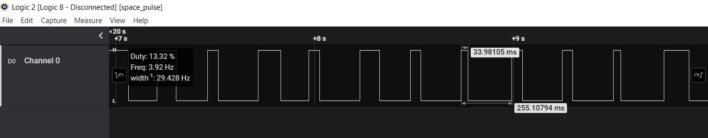
Loading the capture in Logic 2 and mousing over the signal, the software very usefully shows us the pulse period of each pulse. The signal is strange because the pulses are not spaced regularly. Some are long and some are short. For a binary signal, you’d typically try to limit variation in the timings of each pulse to reduce the potential errors.
Because there is only one signal, this presents a challenge for the interpreter. Without a separate clock signal, it is hard to determine if a long pulse is actually two high values or one high value. This presents an advantage for us as we can quickly eliminate common protocols like IIC and SPI that have a clock signal. We can also eliminate typical one-channel protocols that combine data and clock into a single channel as the pulse widths are irregular.
Noting that the pulse width is irregular, we then examine the value more closely.
The total period is a suspicious 255ms, which nicely corresponds to the decimal value of 1 byte. If we treat each pulse length as the decimal value, it corresponds to ASCII characters that upon decoding, reveal the flag. For example 33.98ms can be converted to “!”.
33.98ms -> 33 -> "!"Through fire n gates
The filetype points us to the Logisim software and when we open the file, initially it is a mess of gates and connectors. It is hard to tell the purpose of the circuit as designed.
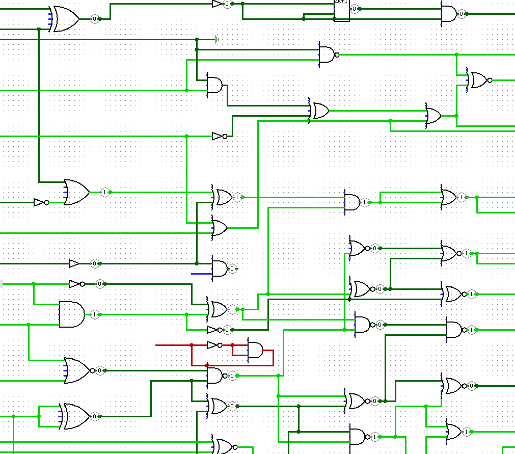
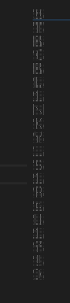
However, if one observes the circuit closer, it can be noticed that there are columns of 8 output values at each section of the circuit.
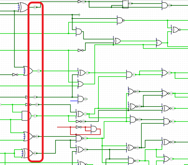
The way forward is to connect the circuit to the outputs of the next column in such a way that each column would form the binary value of the ASCII character of the flag. From prior information about other flags, the first four characters should form HTB{ and the last character should be }. By connecting the circuit at the front such that each column represents the binary values of H T B {, the subsequent characters in the circuit are revealed.
Into the Matrix
I found this challenge to be the hardest to be honest as I was trying to solve it via some knowledge of charlieplexing. However, in the challenge, it was clearly stated that the circuit was fixed and could not be changed. Had I taken that into account, I would have eliminated a lot of dead ends much earlier.
Opening the file in KiCad, the layout of the circuit is presented. In the writeup, there is a line about the circuit being under ‘hard epoxy’ and cannot be changed, as well as a need to work around the limitations of the current circuit.
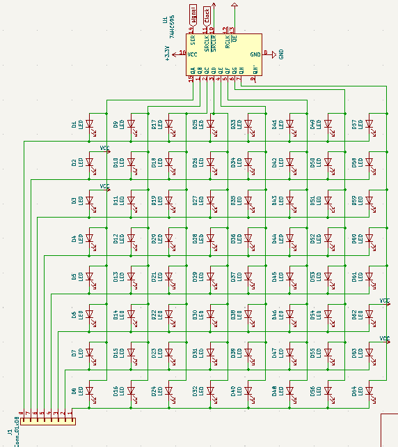
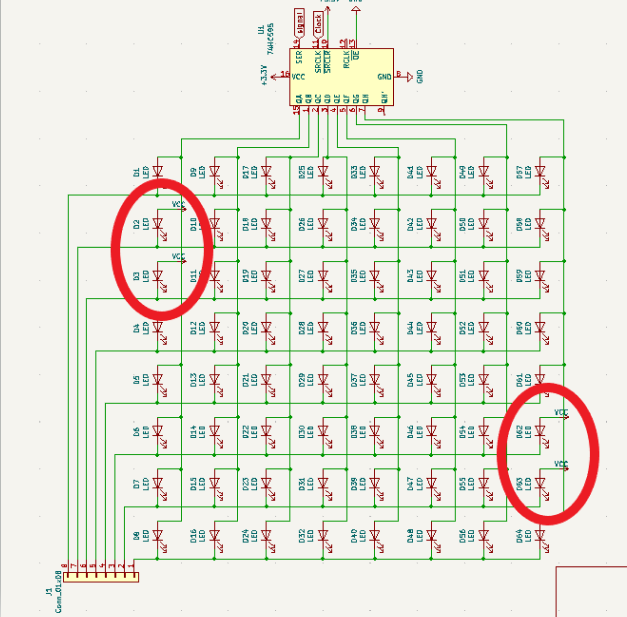
If we examine the circuit closer, we can see that it is a matrix of LEDs but some LEDs are permanently tied to VCC. This particular setup is a multiplexed LED array. The IC is a serial to parallel output IC, which means that it takes in 8 bits on the input, and applies it to the output channels.
The way the circuit works is that the Integrated Chip (IC) at the top of the circuit controls which columns of the LEDs are lit, while the connector at the bottom controls which rows of the LEDs are lit.
Another piece of information is a stream of input signals that is provided.
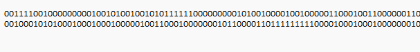
Using metadata analysis, we find that it is 1280 characters, which is 20 units when divided by 64, the number of LEDs in the matrix. The intuition is that the signal will be applied to the matrix and the character will be revealed on the LEDs of the matrix.
Examining the first 64 bits, we notice that there are two bits set on the first value of two lines, and two bits set on the last value of two lines. This corresponds to the broken LEDs in the circuit that are always on.
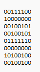
After a few rounds of trial and error, we figured out the order for each set of 8 lines which revealed the flag.
If we had iterated through all the possible values without the benefit of these broken LEDs, we would have needed to iterate 8!= 40320 times. With these LEDs, it is 2 x 2 x 4! = 96 possibilities, a more manageable set. Since we also know that HTB are also initial characters, we can use that to further reduce the difficulty in our guesses.
order = [4,1,6,7,0,2,3,5]By rearranging each row of 8 bits in this order, it creates a picture of the flag.
Secret Codes
This is another signal analysis puzzle. Following the steps that we established earlier, we can eliminate the possibility of signals that need more than 1 channel to operate - IIC, SPI, etc. With Logic’s useful decoder modules we can also quickly iterate through some protocols on the digital signal such as:
- One Wire Protocol
- Asynchronous UART (TX → RX)
However, if we examine the signal more closely, we can see some regularity in the pulses.
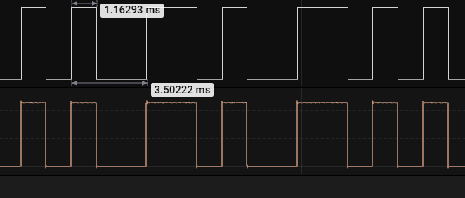
There are consistent short pulses followed by a long pulse that is approximately 2x of the short pulse. If this were encoded as binary values, we would expect that there would be greater variation in the signal pulses.
This is a characteristic of Manchester encoding, and by playing around with some of the settings of the decoder module, we can get the first part of the code.
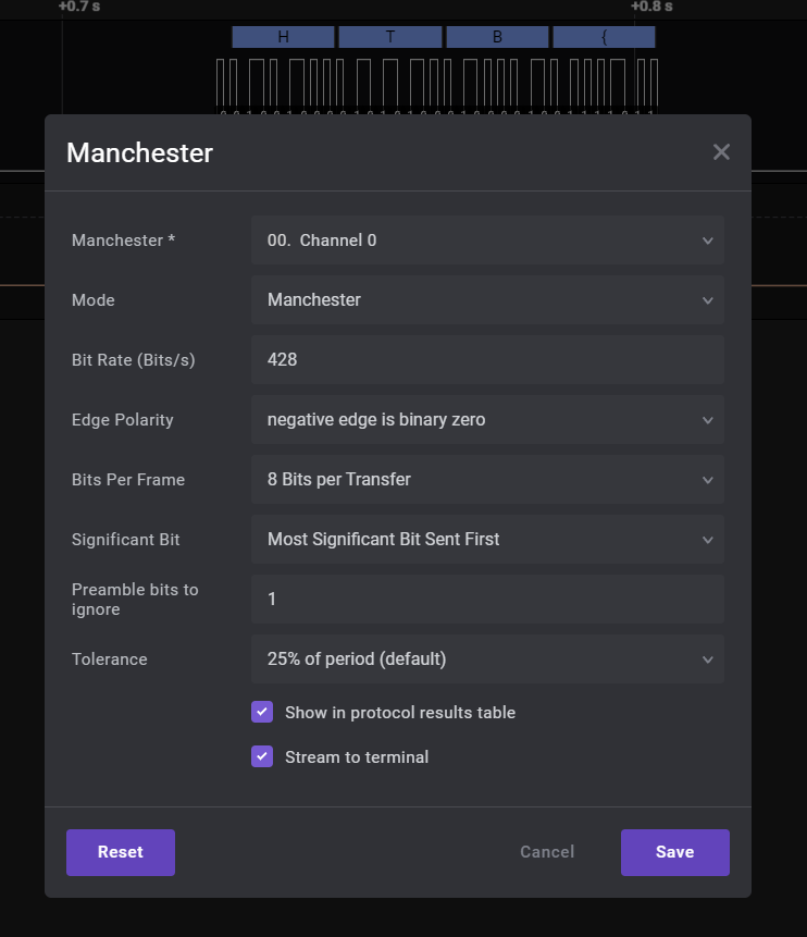
The digital code is only provided in the first part of the message, with the rest of the message in the analog channel. Unfortunately the decoder doesn’t work on the analog part of the channel, so the challenge is to process the analog signal into digital signal, and apply manchester encoding to the digital signal to get the flag.
I decoded the manchester signal manually because it was a bit faster, and got the flag in the first try.
Conclusion
This was my first time participating in a CTF and putting my knowledge of hardware to work in this manner was a little foreign to me but I really enjoyed the process of figuring out the puzzles.