Cyber Apocalypse 2023 - The Cursed Mission (Hardware)


Having some experience last year, the going was easier this year as I knew that I was looking for and how the flag might be encrypted. The following are my solutions for the hardware category of the competition.
Timed Transmission
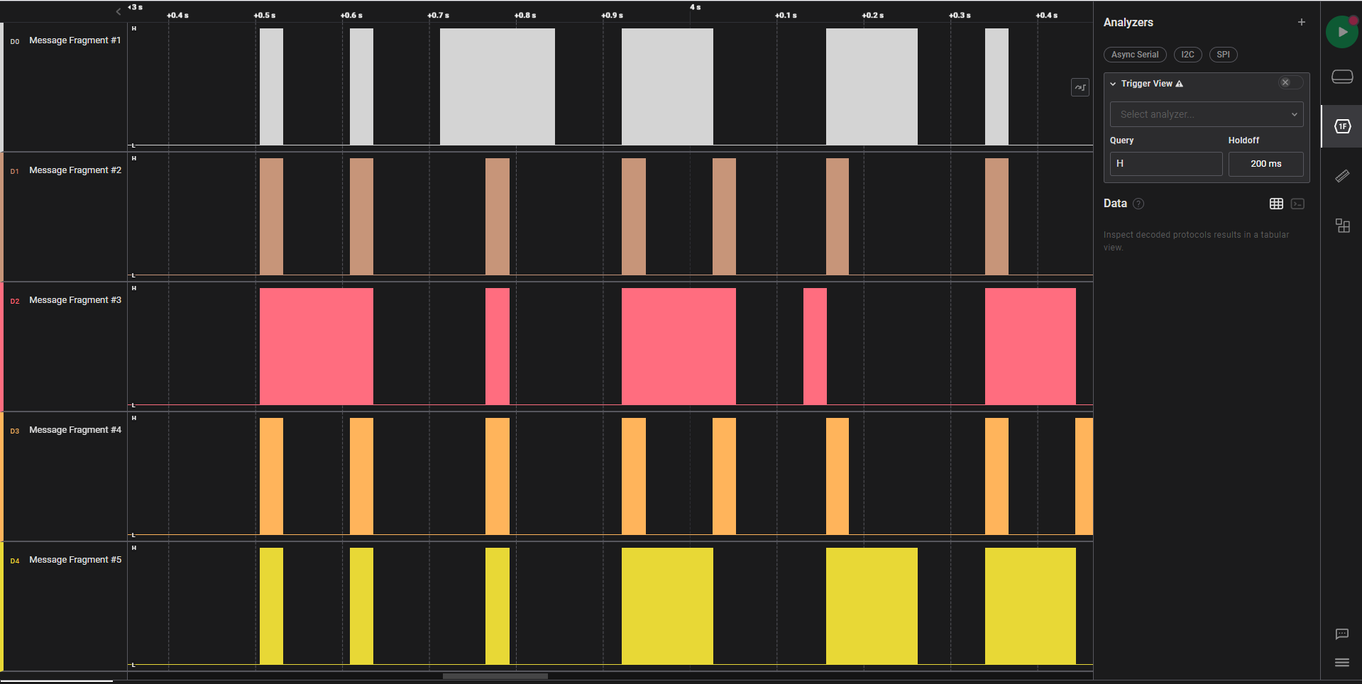
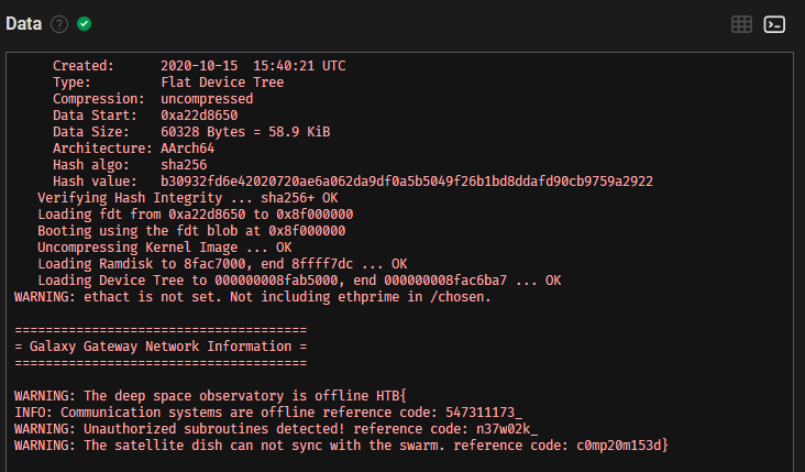
Downloading and running Logic Two from Saelae reveals the flag if the signal capture is rearranged from bottom to the top and you zoom out. It is certainly not a usual method of analysis but an interesting CTF variation nevertheless. One hint is that the signal is not varying in frequency and analysis with the serial decoder results in gibberish, so it is unlikely that any messages can be stored in the signal itself.
Critical Flight
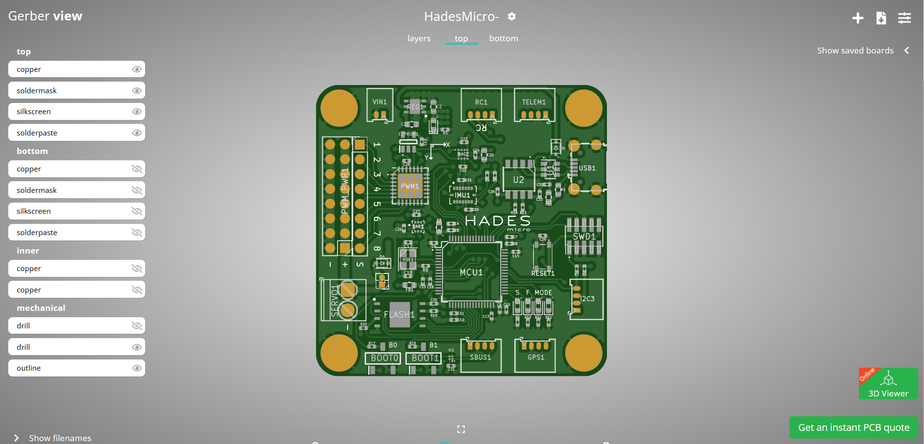
The files provided for this challenge are Gerber files, which are used for the production of PCBs. Loading these files into a Gerber viewer reveals the following.
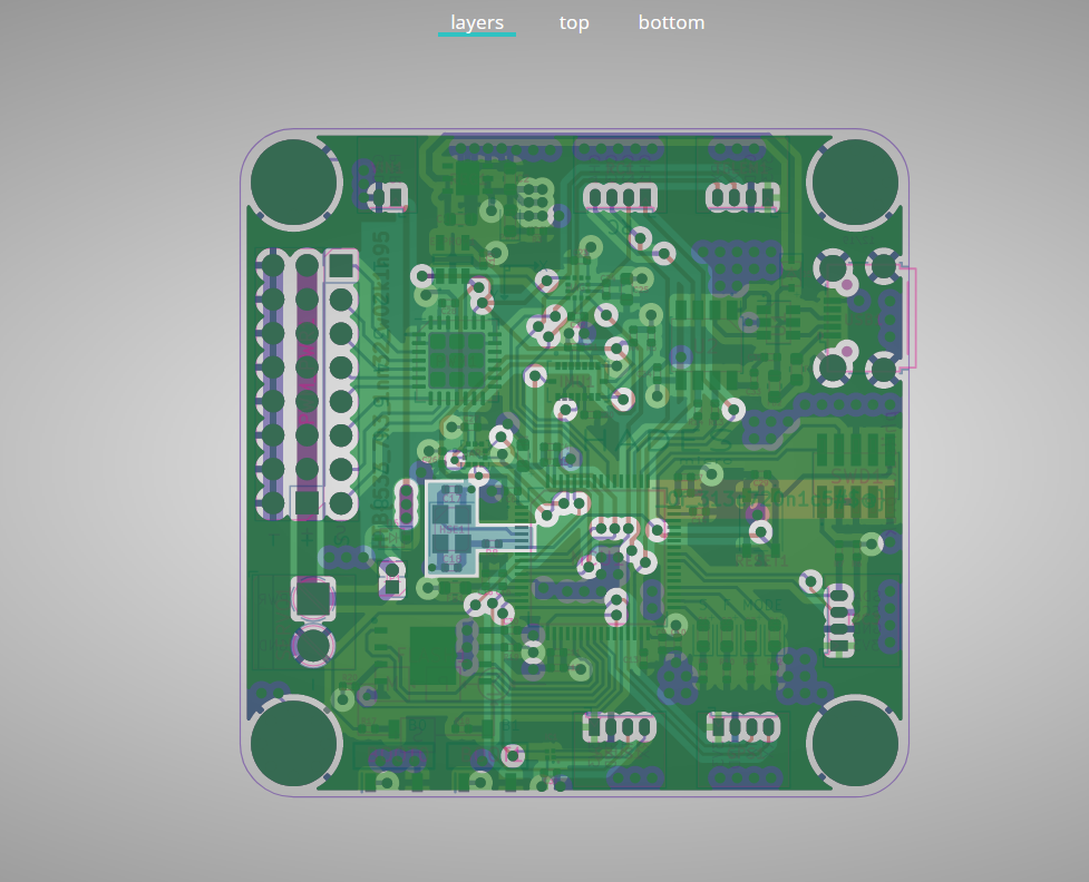
Viewing the PCB by layer indicates something interesting
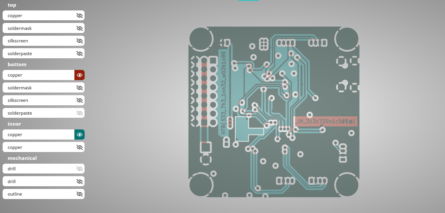
And if we turn off all layers other than the copper layers which are used for the ground planes and signals, it reveals the flag. This is hinted in the challenge description that the boards are not working, therefore there might be an issue with how the board was laid out.
Debug
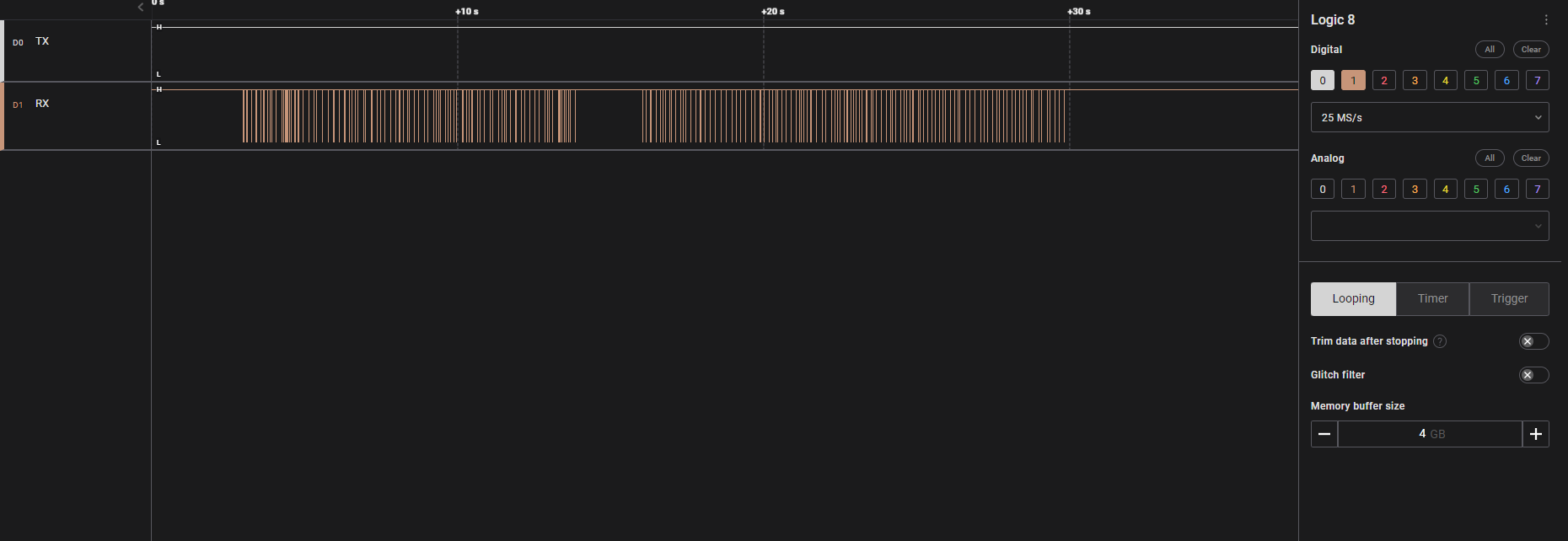
Opening the file with Logic Two reveals a signal capture of two pins TX and RX. This strongly hints that it is a UART or Serial capture.
If we insert the serial analyzer without modifications, it reveals that there is a framing error.
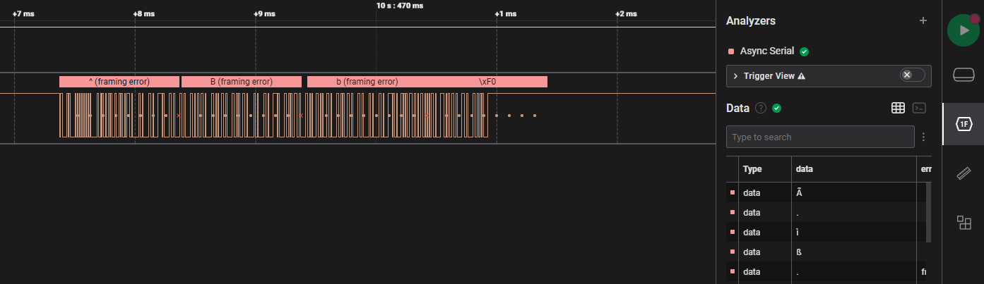
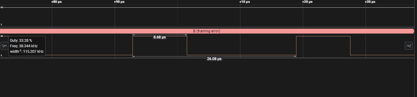
Looking closely at the signal, we can see that one pulse suggests a frequency of 115.207kHz. This is close enough to the standard baud rate of Async Serial devices, the other common one being 9600 baud. This a common theme for HTB. Updating the analyser reveals ASCII characters.
After changing the baud rate, we can obtain usable data.
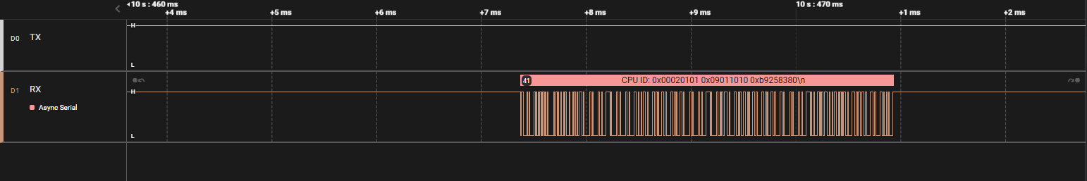
Viewing the data as a terminal output, we find the flag.
Secret Code
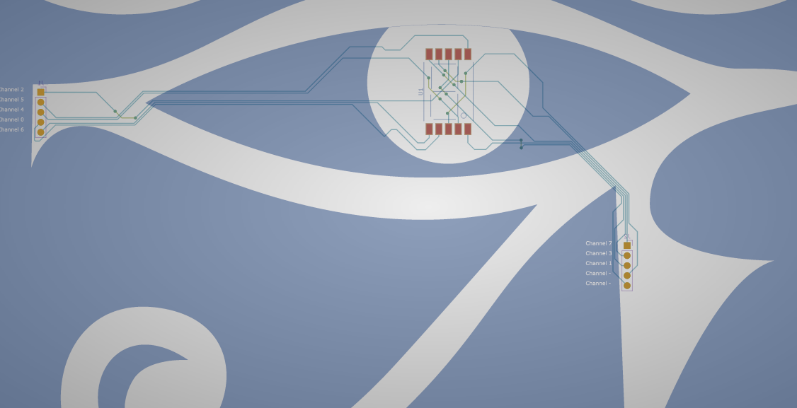
The Secret Code challenge comes with a capture and a zip file for gerbers. Opening the gerber file reveals the following layout. One hint about this IC is there is an 8 written into the outline for the chip, indicating that it is a 7 segment display.
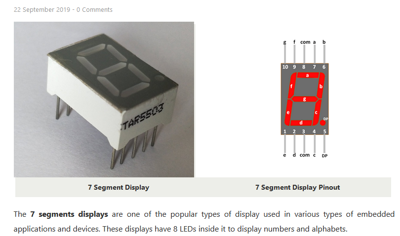
Matching the pinouts to the channels and the signal capture, we can map out how each combination of signals represents a value on the 7 segment display.
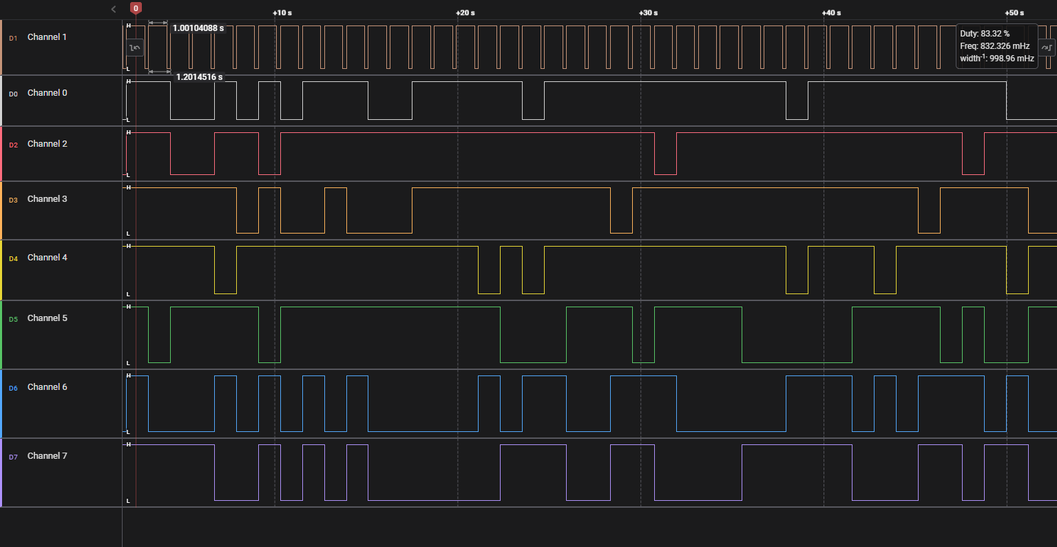
To decode this easily, we can identify the moment when channel one goes from low to high and take in the values of the other channels and reference back to what would appear on the 7 segment display. Processing it in Python reveals the flag.

HM74
Downloading the files for this challenge reveals a Verilog file that we can view in Notepad.
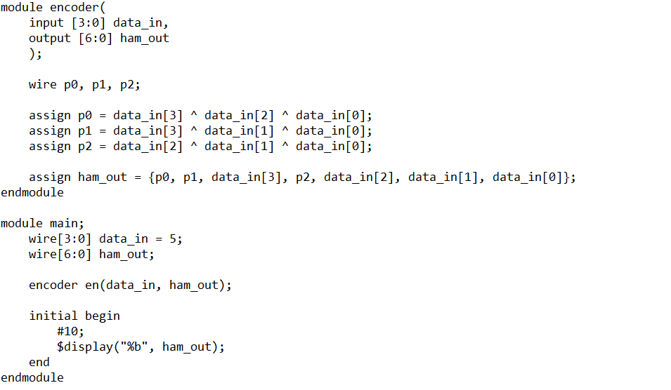
This describes a Hamming 7 4 encoder. A Hamming code is a self-correcting code that can correct one bit of data by comparing the calculated parity values vs the transmitted parity values. By doing so, it can tell you if there was an error and where the error would be.
For this problem, we are not guaranteed that the transmitted code has one and only one bit of error. In fact, even after writing the decoder and plugging it into the output of the Docker instance results in ASCII gibberish.
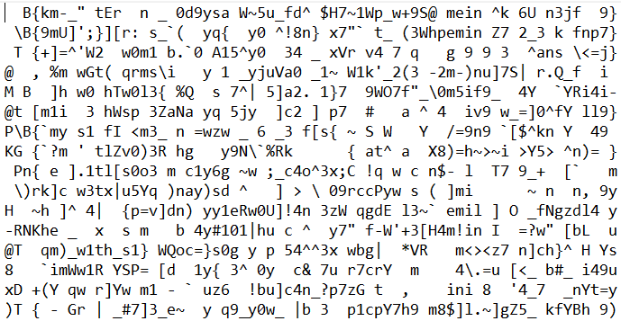
However, quite hopefully we can see some vestiges of the HTB flag. This can probably be explained by the fact that even after error correction, there are some sequences that are too corrupted to be retrieved, and when in doubt, retransmit!
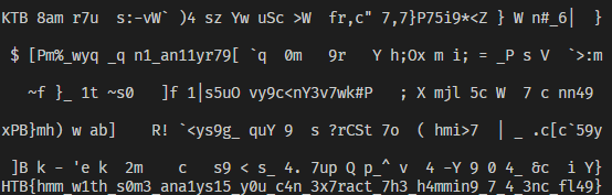
I collected about 10 minutes of data and then determined the most frequent character for each position.
So that wraps up the hardware section for me! I found HM74 to be the most challenging, followed by Timed Transmission as it was not intuitive to me that a flag can be encoded in such a manner.