Design Analysis - Bluetooth Button
A design analysis of a cheap bluetooth button used for finding lost objects or activating remote cameras. This is actually quite a well designed device, featuring a lot of Poka Yoke design elements.

Recently I got my hands on an intriguing device. It was described to me as a Bluetooth Button, but I couldn't figure out how it worked because no instructions were provided. It was given out at an event, which meant that this was quite a low cost device. I decided to take it apart for analysis.
Research
There are several iterations of these devices floating on the market. One of them is the iTag device, or the camera shutter Bluetooth device. These devices are available from eBay or Aliexpress from $3 to $1. From some online chatter, it seems like dollar stores actually stock these devices. Because they are so cheap, some people have repurposed them as single purpose buttons, for example, to track inventory or to activate a device remotely.
Summary of Features
- Using dots to indicate the start and end of the rotating motion.
- Turn to lock and unlock hinges
- Mating connectors used as locating points on PCB
- Snap fit button that only fits in one orientation
- Close integration between PCB and housing design
Opening up the device
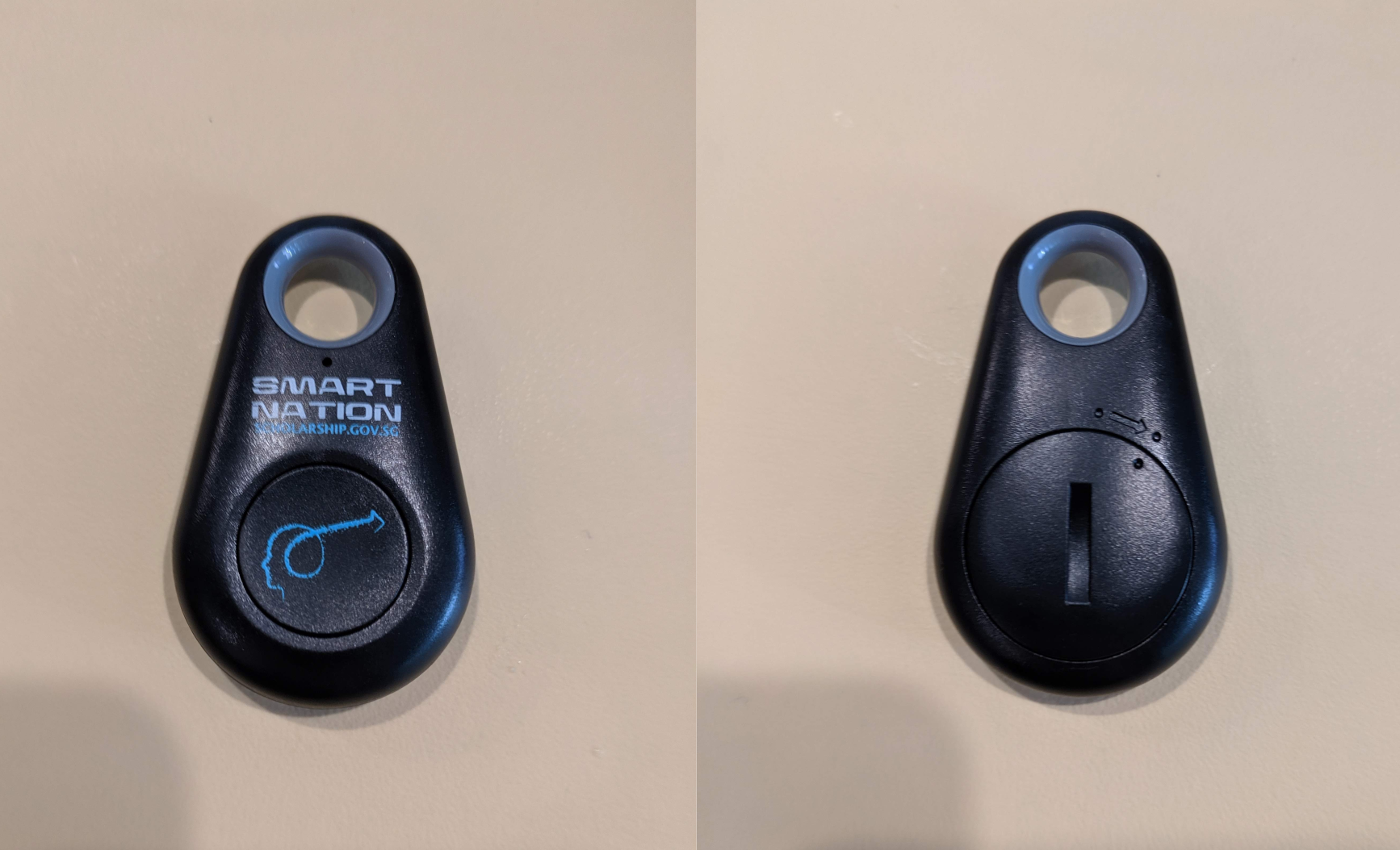
The button is simple, made of molded plastic, the front has a button, and the back has the cover for the button. There is an indication of how the cover is supposed to be locked, which I found very useful when aligning the cover and knowing where to stop rotating.
The device is held together purely by a friction fit. By using a thin screwdriver, I was able to wedge it between the two halves and pry the entire device open.
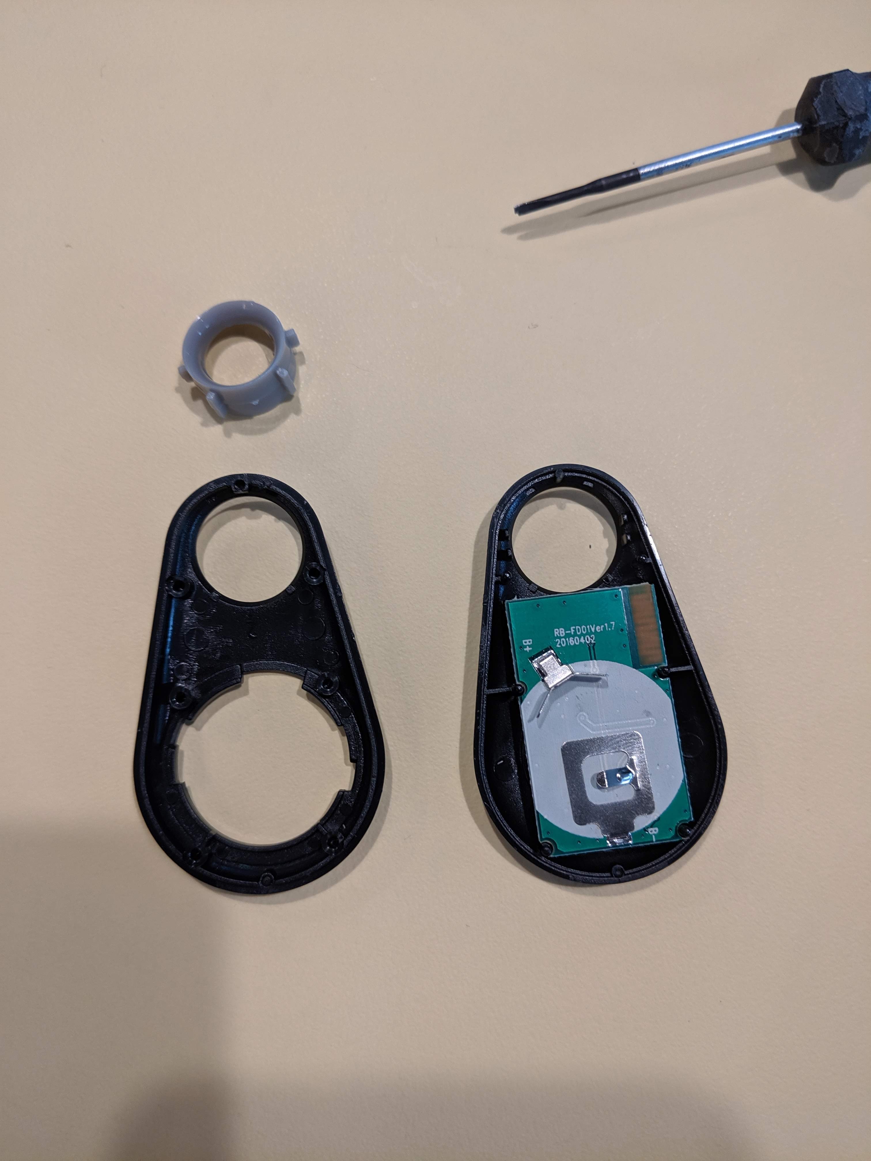
The PCB is held in place by locating cuts, which fit into the locating pins that hold the two halves of the device together. 4 such pins are used to locate the PCB, but there are a total of six such pins. The device disassembles into three parts with the keyring hole being its own part. I believe because the keyring hole has a curved interior surface, this prevents it from being part of the case, otherwise either side of the case it is molded with would have trouble being removed from the mold. Some ribs are used to strengthen the locating pins.
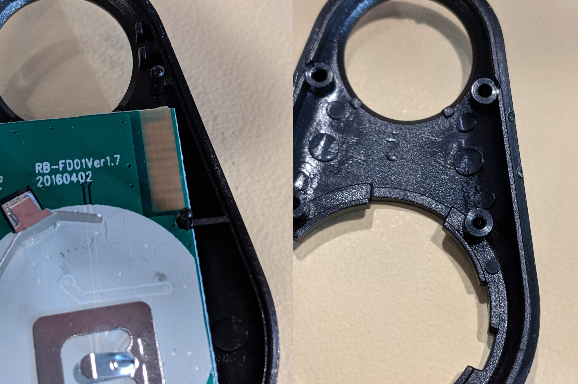
The ridges help to hold the battery securely in place. In fact, I found that the battery was quite a snug fit.
Also notice how the two parts are mated together. There is a ridge on one side and a corresponding groove on the other side.
Buttons
Removing the PCB reveals the physical button mechanism below. There are a few ways to design buttons. One way is to use a cantilevered design. This method uses a snap fit with some clearance. This button is rather well designed because it is designed so that it only fits in with one orientation, and it is up. The clicking action is also quite solid, so the clearance is just enough for the SMD mounted button to be depressed.
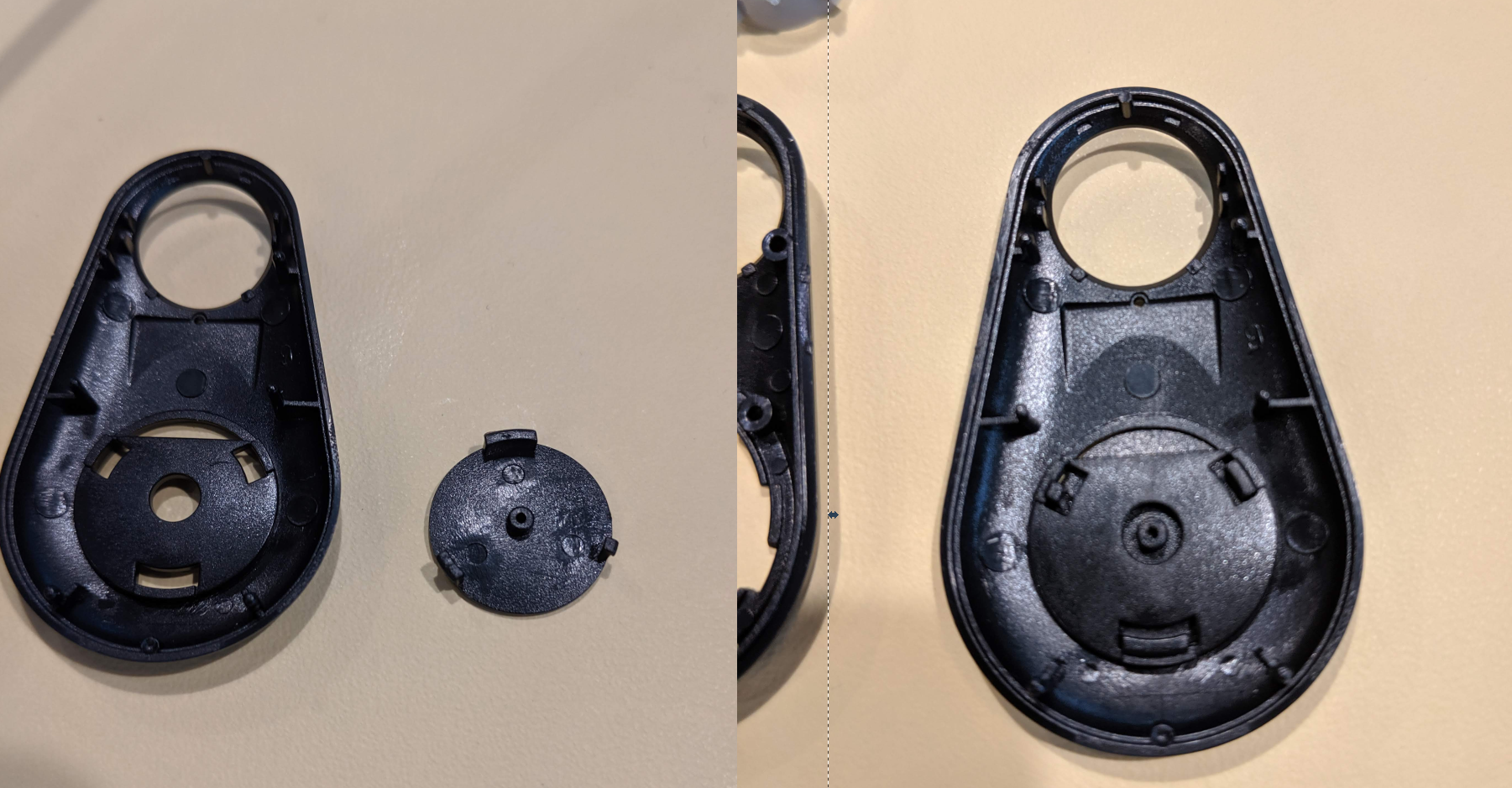
The snap fit ensures there is minimal wiggle because it limits the rotation and lateral movements. It also helps to locate the center rod which is used to depress the center SMD button.
Electronics
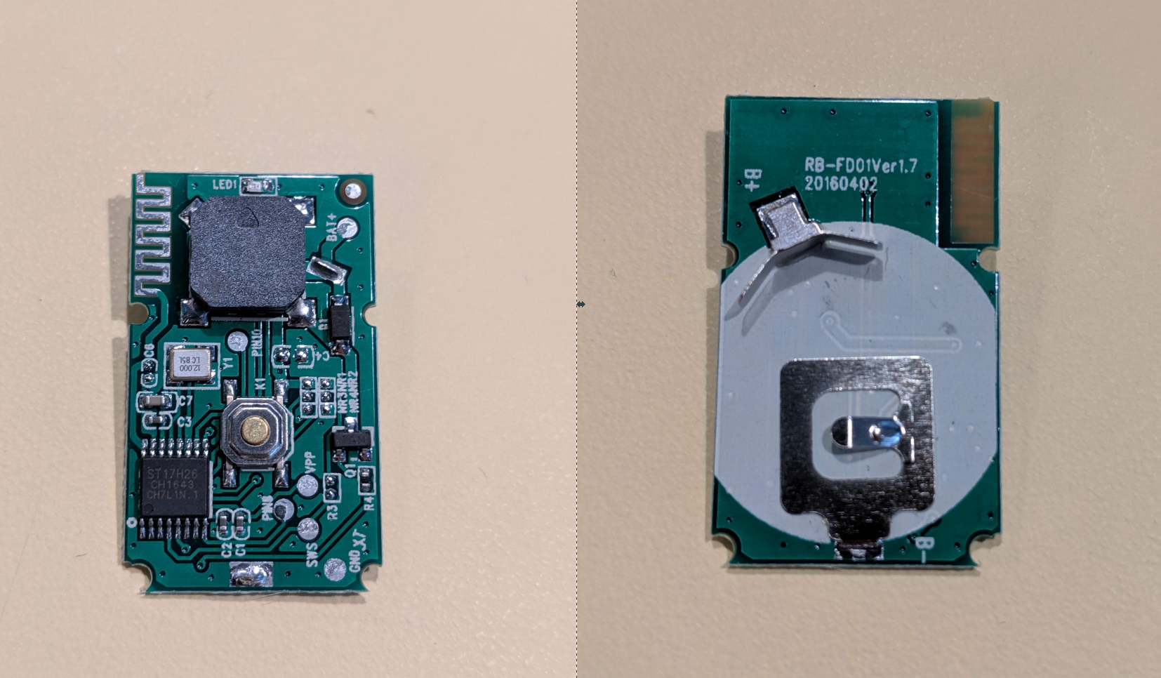
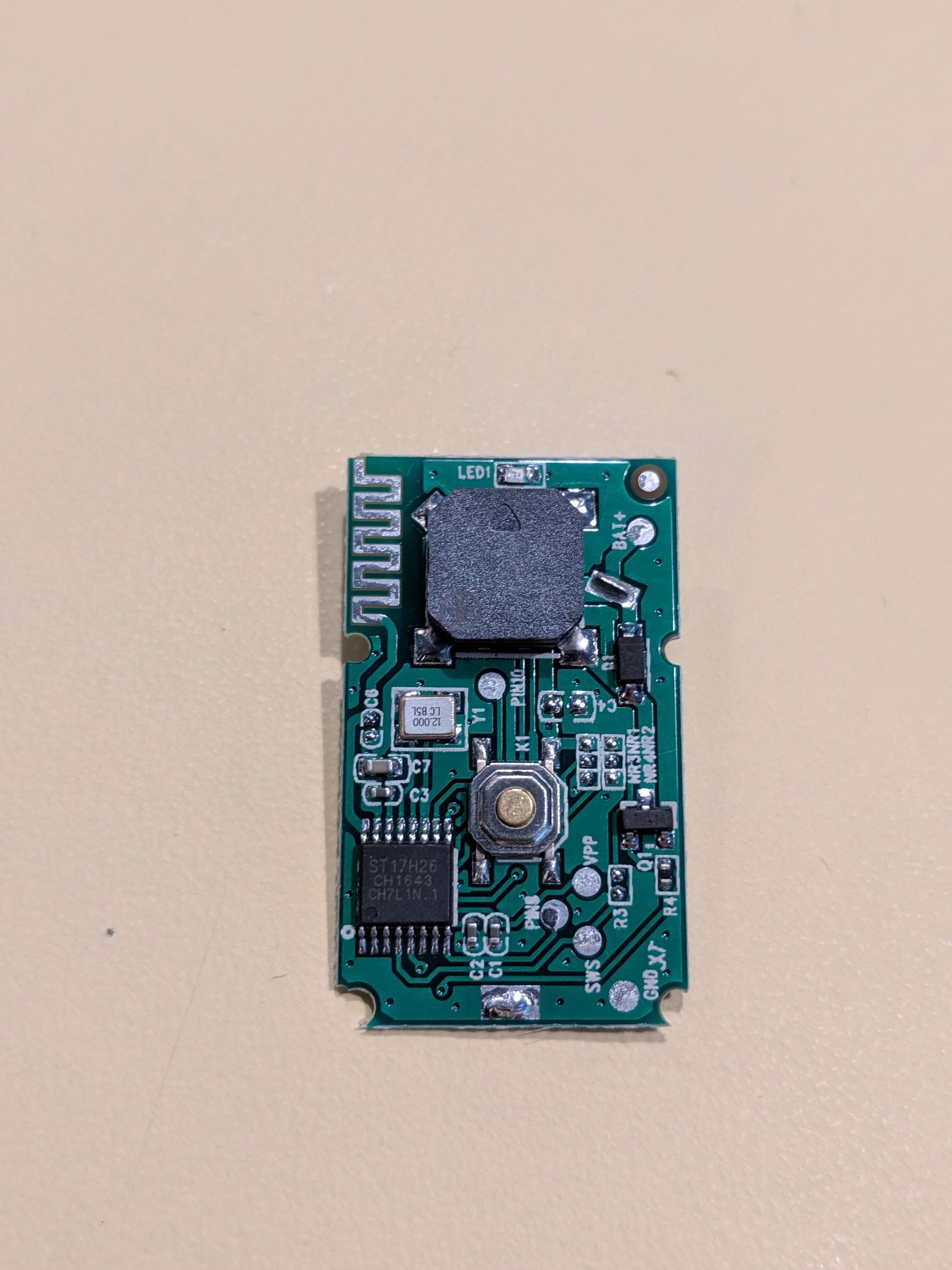
The electronics is pretty simple. There is a black SMD mounted buzzer on the top, with a pushbutton in the middle of the board, and a ST17H26 Bluetooth IC with a PCB trace antenna. On the bottom side there are a few soldered tabs that help to hold the battery.
The Bluetooth IC appears to be unavailable from the usual suspects (LCSC and Aliexpress), but can be found at more specialized retailers like Alibaba or Taobao, where they retail for $1.00 in single quantities. The board appears to be manufactured in 2016 as seen from the silkscreen. There are quite a few datasheets online, and quite amazingly there is some information from the manufacturer, LENZE Tech, and some code for an SDK.
Battery Holder
While it doesn't seem to be required, however the battery area is marked out in white silkscreen (possibly for design purposes) while the battery itself is held in place by the case. In a lot of my designs I use a battery mount, which takes up a lot of space on the PCB and doesn't look very nice, and is hard to integrate with a case. This is one way to mount a battery.
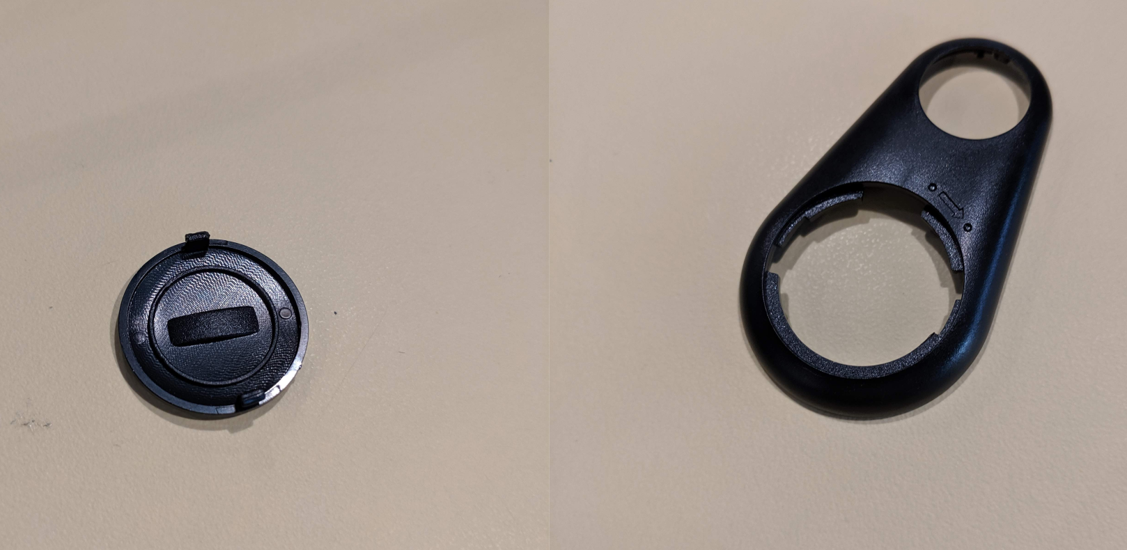
The back of the battery cover reveals a bulge that is formed by the depression on the other side, used to turn the cover for release and locking. Another thing that this bulge is used for is to hold the battery against the contacts securely, along with the ring around it. The cover uses a snap-fit hinge, but its mating end is designed so that it turns to lock and unlock.
Conclusion
For such a cheap device, there are quite a few design techniques that can be learned here. For the case, there is quite a bit of design that went into locating parts easily and holding everything together, and it showed quite a close integration between the PCB and case design through the elements that interacted with each other. I believe this is known as a Poka Yoke design philosophy, in which things are only designed to fit one way. For such a cheap device, it is quite surprising to find out that it incorporates so many design elements.
A potential use for this device is to be a replacement for the Amazon Dash button, which was discontinued, but was really useful for awhile as a single-purpose WiFi-enabled Button.