Towards automatic generation of EAGLE parts
How I tried to automatically generate parts quickly in EAGLE and succeeded! (and failed)

Library creation in Eagle is often a tedious affair, which is why I avoid it as much as possible, often going out of my way to find preexisting libraries to integrate into my own mylib.lbr. But searching for these libraries can be hit or miss, and the quality is variable. You can get some really good libraries from Sparkfun, Adafruit, or that excellent microbuilder.lbr, but you might just as likely not find any parts especially if you are using an uncommon part. So what do you do? Often I trudge back to EAGLE and reluctantly start to create my parts. I start have to overcome some activation energy before I can really get down to building the board.
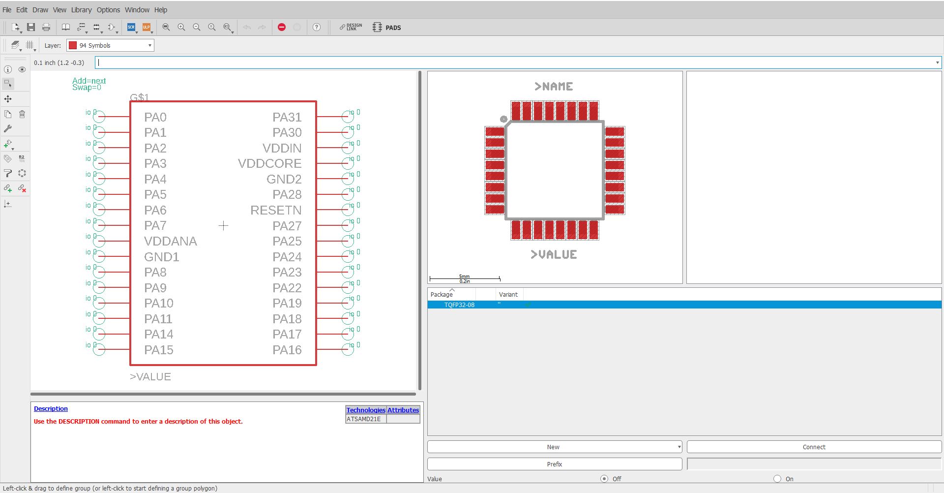
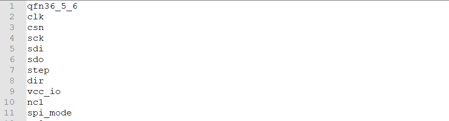
Each pin on the IC has a function. The function is indicated by the label such as PA0, VCC, GND... These functions relate to a pin on the IC, such as the first pin on the IC is VCC, the second pin on the IC is GND... etc. However, generating the symbol (a schematic drawing of the IC), footprint (the pads and the holes that go on the PCB), and the device (connecting the symbol and footprint) can be a very tedious click and drag affair.
So I decided that I would build an automated pipeline that would help me do part creation. My idea: you take a screenshot of the part you want to make, and the part appears in your library.
TLDR; OCR is bad, PDF analysis is hard, user-created CSV(s) are way more reliable.
Motivation
Most companies provide datasheets to let engineers do schematic capture for their chosen ECAD software. Some companies provide libraries of their parts, but these are limited to enterprise-level software like Altium. If you are using Kicad or Eagle, you are usually out of luck.
It would be lovely if there were some common format that all manufacturers provided for their ICs, for example, a simple CSV file of the pin number and functions would have made automating this process 95% easier, but unfortunately, nobody seems to be doing this.
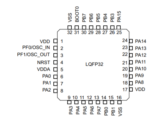
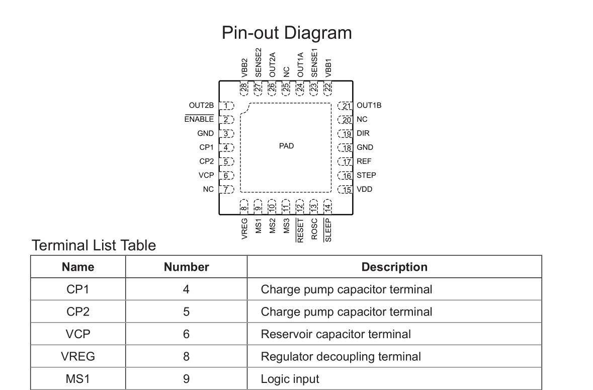
The key similarity is that all datasheets have some sort of picture of how the pins and their associated functions are laid out with respect to the physical package. This means that in an ideal world, we can take a screenshot of this image and have it spit out the CSV file.
OCR troubles
The problem, funnily enough, is that OCR technology is not good enough to recognize screenshots of numbers. Sometimes it doesn't even pick up numbers. Even little details like curves and lines of the symbol is enough to mess the OCR up. I felt this was interesting because having a screenshot of text on white background is pretty much the ideal OCR case. You don't have reflections or blurring, and the background is of a consistent color and the edges are clearly defined.
OCR Tools:
- Tesseract
- Google Cloud Vision
- Azure Cognitive Services
- Random internet OCR services (they appear to use tesseract)
Unfortunately having gone through all the various OCR tools, the result is still pretty bad. I want to say on a typical screenshot of a part like this you get about 50% accuracy:
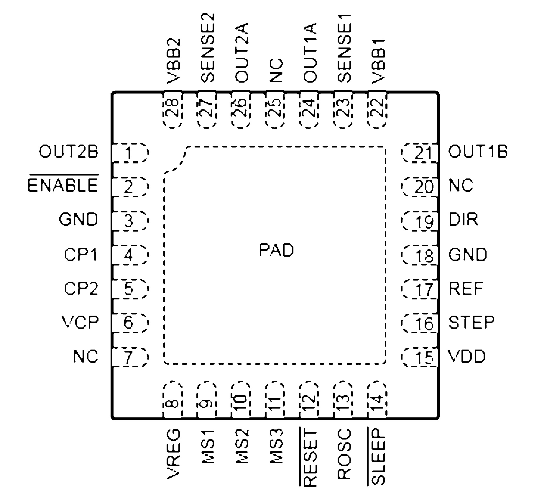
and on a part like this is drops to about 20% accuracy:
Preprocessing the images to remove lines only gave a marginal improvement of about 10 ~ 15% simply because there are so many styles.
Example
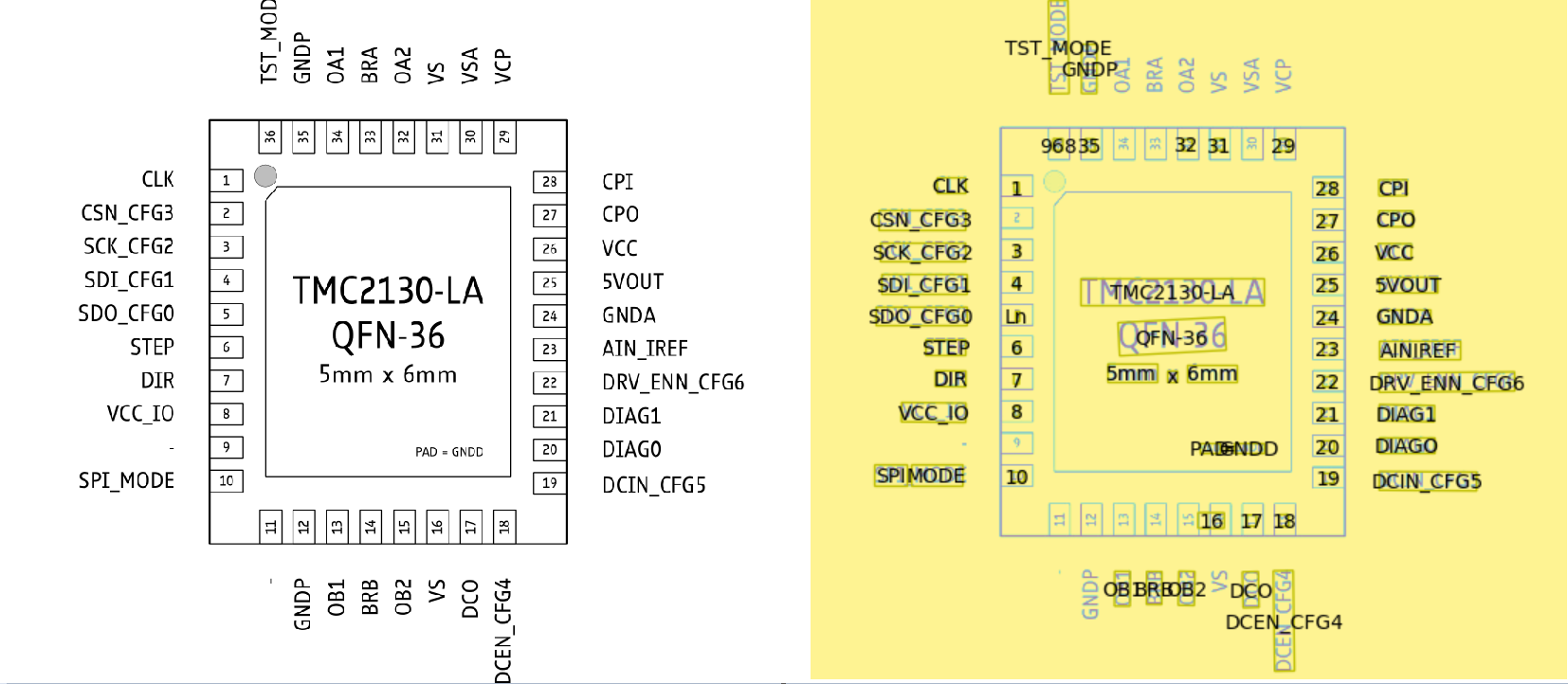
Some problems with this:
- Not all numbers are identified
- 36 is incorrectly identified as 968
- Dashes, which indicates no connect pins, are not identified
- 8 lables are not identified
- 5 is identified as Ln
So that's pretty much unusable
That's right. After a few nights of experimentation, I reluctantly put aside OCR and pivoted to the next structure in the datasheet that might yield a good result: the table.
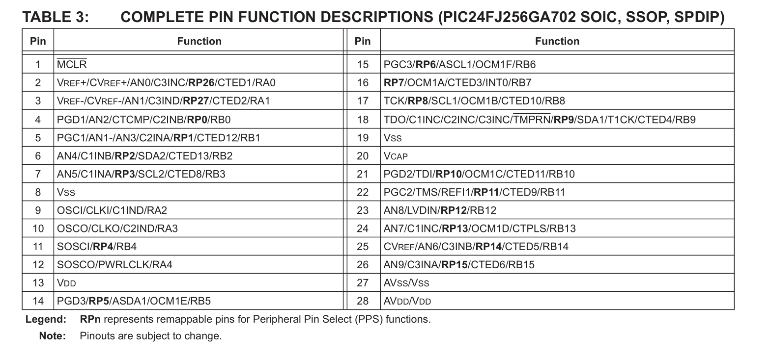
Now the table yields quite a bit of promise:
- Text is not rotated
- Ordered display of pins and functions
Again, in an ideal world we would be able to take a simple action and the part should automagically appear in our library. But reality rears its head again!
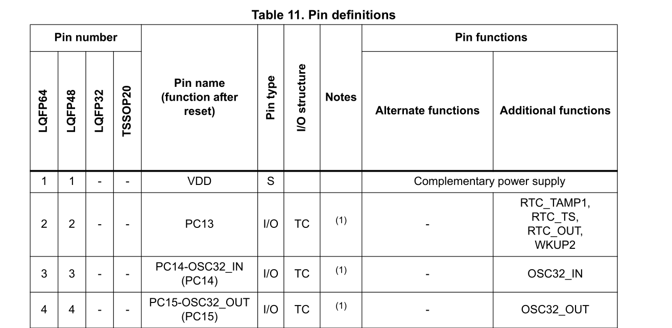
It's hard to capture a screenshot of the whole table, and sometimes the table spans multiple pages so multiple screenshots have to be taken. However, now we have additional information in other columns, such as any additional functions, or duplicated header rows. This all requires code to strip away, and that's assuming OCR works 100% of the time, which it doesn't.
Camelot to the rescue!
It turns out there is a way to perfectly capture PDF tables, and that is instead to use a library specifically designed for that: Camelot
Camelot utilizes the underlying structure of the PDF to extract information by guessing where each cell is based on the lines in the PDF. There is a whole paper that is written about this by Anssi Nurminen.
When it works, it works flawlessly. Which is great, except...
Too Specific
Unfortunately, the new problem now is that we have too much information. Some tables have extraneous details, some have repeated headers, others stretch over multiple pages... All we want is a column with the pins and another with the columns, but without specific templates tailored to each table, this is prone to failure.
Back to the drawing board
I still like my original idea of taking a screenshot of the page. After some searching I managed to find a library that would let me work with the PDF in python. OCR is a little too error-prone at the moment, but the table data relies too much on prior knowledge of how the table is formatted.
An alternative is to crop a section of the PDF, and if I focus on the area with the diagram of the layoout, I can essentially obtain a perfect "OCR" of each word and it's location by using the underlying PDF data to identify where each character is placed within the PDF. From there it is a simple matter of correlating each described pin function with each pin number.
This method works pretty well to extract information from the PDF if the area is selected correctly. The only drawback occurs for word detection. You have to specify the threshold limits for word detection, and this can vary depending on the size of the image and the orientation of the letters. Again, this can sometimes fail when there are large swathes of horizontal text, or text that have different sizes.
The solution between chair and keyboard
There is the unspoken solution between the chair and the keyboard. The user! It is not a whole lot of effort to type up a CSV file, especially since you already have to type it out in the software.
This way ensures that the pins are correctly labeled and ordered each time. Other methods require some user intervention to clean up the data, and this can sometimes take awhile, especially if the performance is bad.
Some informal tests show that it takes approximately one minute to key in 30+ pins. The functions are listed in order of the pin number, so only the functions need to be entered. This is a far superior way to generate pin layouts as compared to OCR or PDF table interpretation, considering the level of user intervention required at this point in time. Since I'm not processing thousands of parts at a high frequency, I think this is an acceptable, if lame, tradeoff.
It is still interesting to note how Occam's Razor is in full effect here. The CSV is the simplest method, and yet it has minimal errors, and has the least amount of dependencies.
Footprint Creation
Package creation is also quite formulaic. There is usually symmetry through one or two axes, which makes the generation of pads significantly easier. Given some basic parameters like the pad size and distance from the center, the whole package can be created on the basis of symmetry.
Pulling it all together
Once the footprint and the symbol is generated, the device ties them together, linking the symbol on the schematic sheet to the layout in the PDF. Once the package pins have been correctly allocated, the device is then inserted into an existing .lbr library, and it is ready to go!
Limitations
- User input is required to validate the output of the program.
- Only saves time for more complex parts, completely useless for two pad parts like resistors and capacitors.
- Pinouts are not organized
Conclusion
And of course the following turned out to be true:
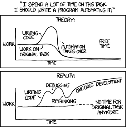
and this:
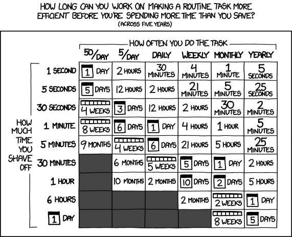
I have spent more time on this project than I would have saved. Assuming that it previously took me 10 minutes to create the part, it will now take me 1 minute. But it was a great learning experience, and if other people use this tool, it would have collectively saved more time!
The nice thing about using CSV is that in the future, if I manage to get OCR working, I can just take the output and plug it into my current program as an input, so it is still extensible in a way.