How to program an ATtiny85 easily
How to program an ATtiny85 in Arduino easily with micronucleus.

This article was first written in 03/27/2017. It has been updated in 2019.
The ATtiny85 is a small 8 pin DIP/SOIC microcontroller from ATMEL, now Microchip. While the limited pin-count might seem to be a limitation, however, it is perfectly suited for small tasks where a larger microcontroller would be an overkill. Some examples include reading a few sensors and toggling a light. The small footprint also allows space to be conserved on space-constrained PCB boards
ATtiny85s can be programmed in Arduino. There is a commercial product called the Digispark that has been extensively cloned by Chinese manufacturers selling it almost at cost. In fact, buying a Digispark clone is often cheaper than the bare ATtiny85 chip. The Digispark is a standalone board without a need for an external programmer because there is a small bootloader called the micronucleus loaded onto the ATtiny85 chip. The executable, also known as micronucleus on the computer waits for an micronucleus-enabled board to be plugged into the computer and it then programs the ATtiny85.
Tldr
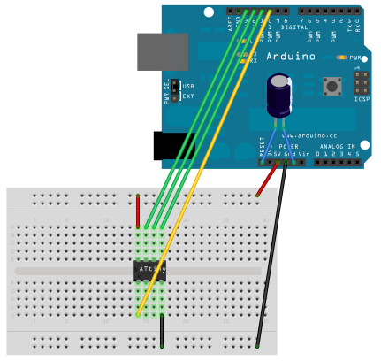
Set up an Arduino as an ISP. Connect the Arduino as follows:
For Windows, if you want to flash the latest firmware, download the zip file from Github, extract, and navigate to the firmware/releases folder and run the following code:
avrdude -c arduino -p t85 -b 19200 -P COM9 -U flash:w:"micronucleus-1.11.hex" -U lfuse:w:0xe1:m -U efuse:w:0xfe:m -U hfuse:w:0xdd:m
- -c arduino: Programming with an Arduino ISP
- -p t85: Programming an ATtiny85
- COM9: COM port of your Arduino, check in Device Manager or Arduino
- "micronucleus-1.11.hex": The file to flash to the ATtiny85.
How it began
I had the idea of stripping cheap ATTiny85 chips from their boards on a Digispark and integrating them onto my own PCB boards because they are easier to program on a pre-made board, and when I'm happy with the result, I can just place it on another board, and voila! Everything should work. Unfortunately, things weren't as easy as I expected.
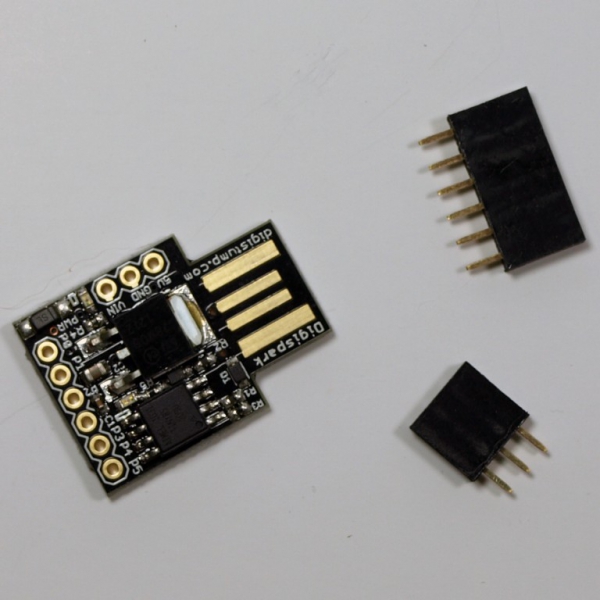
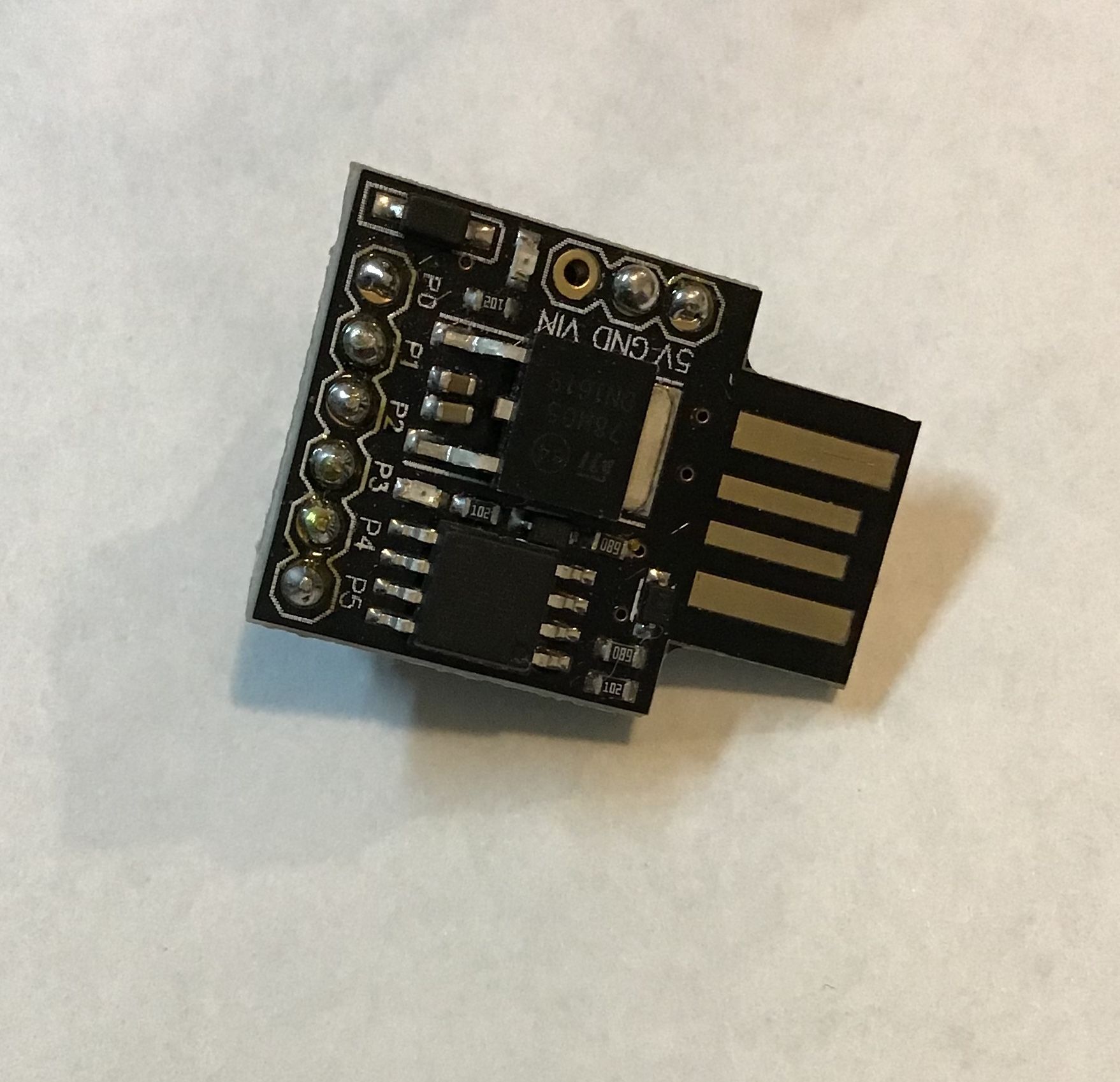
Figure 1. Digispark
The first issue was that the circuit did not work. I could solder wires to the traces to reprogram the ATtiny85, but there were other parts of the circuit I wanted to change, so I decided to buy a breakout board from Adafruit.
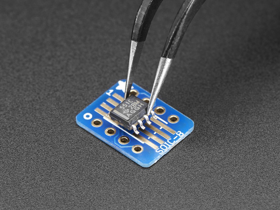
Figure 2. SMT Breakout Board
Of course if you started with a DIP version of the ATtiny85, you wouldn't have to do this.
Lesson 1: Always prototype your circuits on a board first!
Wire the ATTiny85 to the Arduino ISP as follows:
VCC->5V
PB5->10
PB2->13
PB1->12
PB0->11
GND->GND
I tried plugging in the power and LEDs but nothing worked, so I decided to use an Arduino as an ISP to program the blink sketch into the ATtiny85 using another package library for ATtiny85 chips, and the light started to blink.
But one issue was that the internal frequency was set at 8Mhz, and changing it to 16Mhz or 1Mhz caused the time between the blinking to react strangely. I believe has some issue with Arduino assuming that the original frequency is 8Mhz. The reason for choosing a lower frequency was that I wanted to conserve power. A lower frequency results in a slightly lower power draw from a battery, quite important if you are using a battery powered project. However, with the Digispark software, all timings are correct and I was able to set it to the frequencies that I required previously.
So I had to load the Digispark firmware onto the chip. First I tried to turn my Digispark into an ISP.
I tried using the littlewire tutorial on the Digispark forum to turn my other Digispark into an ISP, however it was never able to recognise the other ATtiny85 chip, even though it was registered as a USB device after I loaded the Littlewire program onto it.
So next I decided to use my Arduino as an ISP to load the Digispark firmware. I referred to an Adafruit tutorial for the specific command required to run it. Note that you need the baud rate for the Arduino ISP to work properly!
~$ avrdude -c arduino -p t85 -b 19200 -P /dev/ttyACM0 -U flash:w:".../t85_default.hex"
With a new chip you will also have to set the fuses (add to the original command):
-U lfuse:w:0xe1:m -U efuse:w:0xfe:m -U hfuse:w:0xdd:m
If your tools are new, you should be able to upload the firmware successfully and you should be able to start programming it immediately in Arduino.
If your tool in Arduino is old
I managed to load it successfully and tried to use Arduino to program the Digispark, however it reported that the firmware is too new for the tool. So now we have to replace the tool. From the micronucleus github, go into the commandline folder and run the command to make the micronucleus executable. Now you'll have to locate the old tool somewhere in ~/.arduino15/packages/digistump/tools/micronucleus/2.0a4/micronucleus and replace it with the new tool you just complied. Make sure to backup the old executable just in case you want to revert.
You can also upload the old micronucleus firmware, which is version 1.06.
Locate the old micronucleus program that is called by arduino replace it.
You should now be able to upload the micronucleus firmware to any ATtiny85 chip. The nice thing about desoldering the original chip is that if you do a 1:1 wiring of your ATtiny85 to the board you will be able to upload sketches as if the ATtiny85 were on the board itself! That way you can program and prototype many Atiny85 chips.
Remember once you switch back to uploading code via micronucleus, you need to remove the wires from the ATtiny85 connecting them to the Arduino ISP.
Removing the 5 second delay from the Digispark ATtiny85
Now I wanted to remove the 5 second delay so I used the following release of micronucleus (v 1.11) and the upgrade file micronucleus-1.11-entry-jumper-pb0-upgrade.hex. I used the latest version of the micronucleus executable and ran it with the option of --run. So the code to run in the terminal looks like ~$ micronucleus --run '...upgrade.hex'. In this case, PB0 is pulled to ground to prepare the chip for programming when you finally upload the breathe program. If it is not pulled to ground, then the chip will immediately run the program that is loaded on it.