Assembling LM3914 Power Indicator Display board
How to assemble a LM3914 charge indicator board

The LM3914 is a dot/bar display driver. It senses analog voltage level and drives 10 LEDs, making it suitable for use as a power indicator, and there are a number of products that use this function.

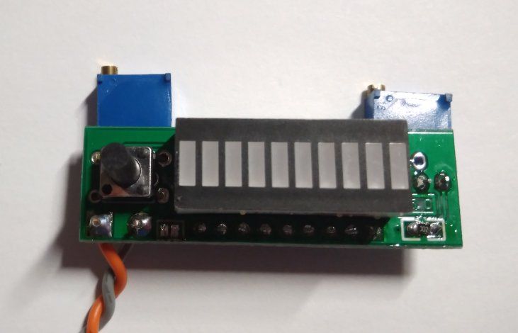
This device is marketed as a 2.4-20V power display indicator on Aliexpress and Banggood. It is a pretty small board, and would be useful in determining the charge on a acid battery or LiPo battery, where the voltage varies with the charge.
However, one problem is that all the instructions come in Chinese! This makes the board hard to assemble and calibrate.
Assembly
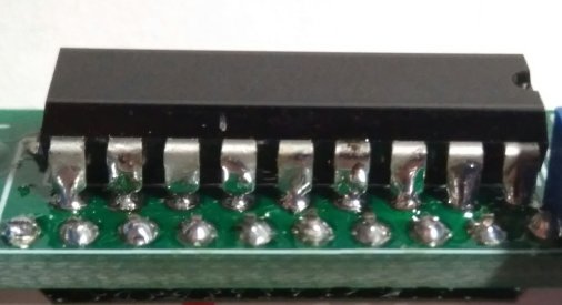
Assemble the LED matrix first before the LM3914, otherwise you will not be able to solder the pins of the LED matrix as some of them are encased within the white plastic shell. Since the pins overlap, you will only have access to the top side of the LM3914 pins on one row, however, it is still possible to solder by soldering the sides of the pins as all the pins and pads are still exposed.
Ensure that the IC is oriented in the right direction. The top of the IC should match the white silkscreen, use the notch on the top of the IC to determine the orientation.
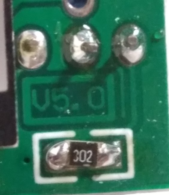
While 2 3K 1208 resistors are provided, only one is required.
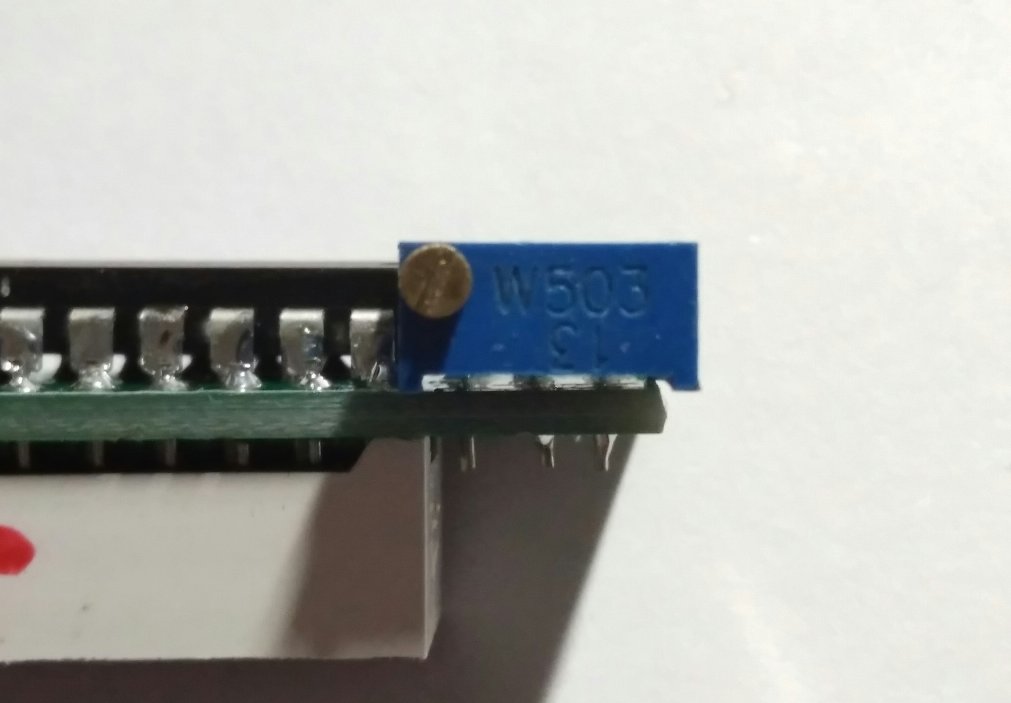
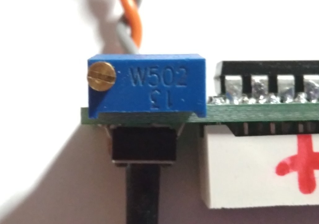
There are two different potentiometers provided, a 5K (502) and 50K (503). Ensure that they are soldered in the right places.
There are two traces that can change the configuration of the board. If you short the trace just under, this will cause the board to be always on. If you short the trace just below the LED matrix, instead of using a single bar to indicate the charge level, a full set of bars will be used. I do not recommend shorting any traces before calibration.
Calibration
Power up the device to the high limit voltage. Now turn the 50K potentiometer clockwise if the LEDs are not lit, and counterclockwise if they are lit. The objective is to turn the 50K potentiometer until the LED closest to the button lights up. Once that occurs, set the low limit voltage, and turn the 5K potentiometer until the bar furthest away from the button lights up.
Calibration is now complete. If you want, you can bridge the solder pads next to the 5K potentiometer so that the bar is always indicating the battery voltage. Do note that the blue LEDs can draw up to 70mA of current if they are all lit up.