An integrated Arduino nRF24L01+ module
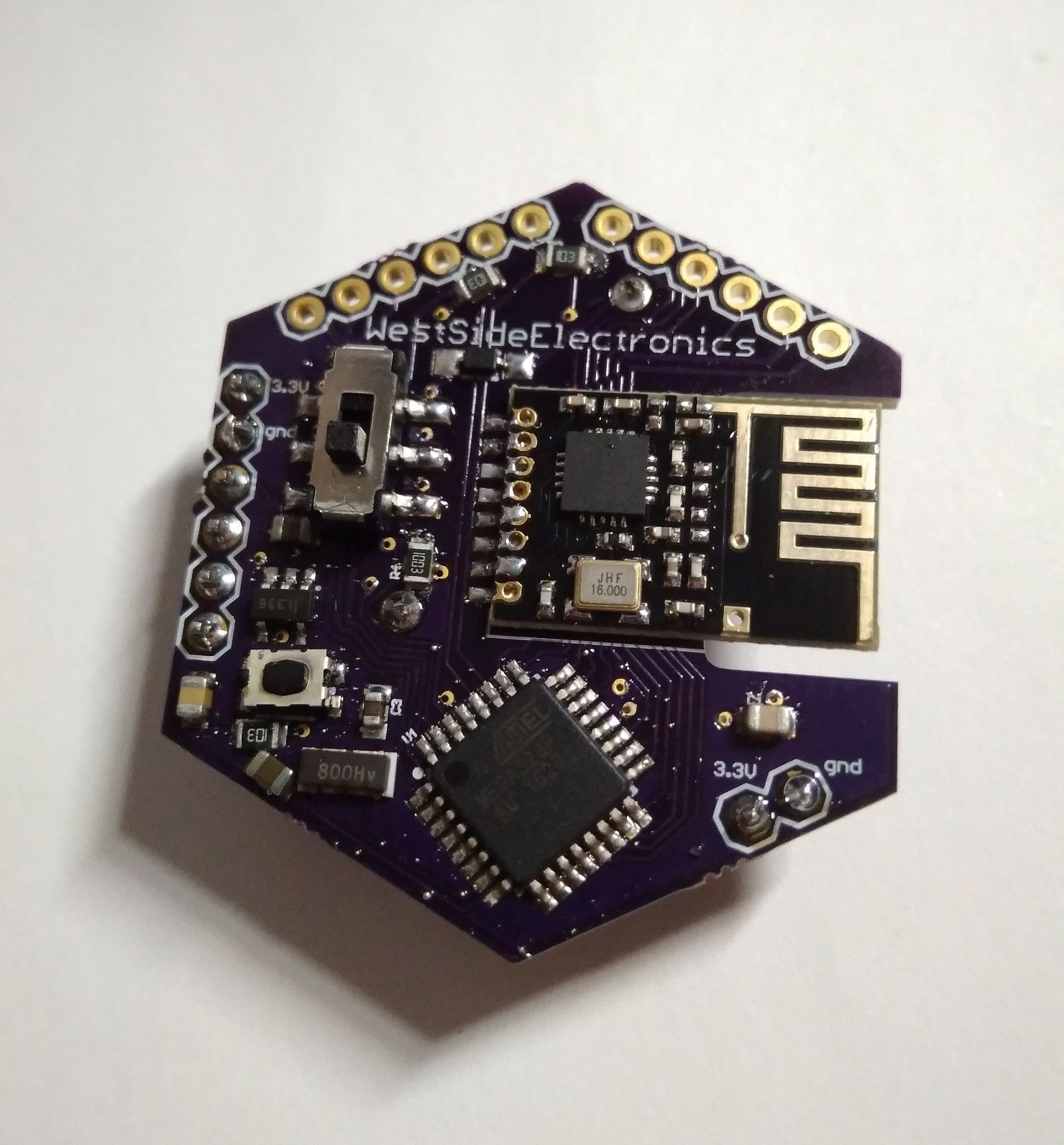
While blinking LEDs can be really fun, wireless communication is like magic. I combined an nRF24 chip with a ATMEGA328P on a PCB.

While blinking LEDs can be really fun, wireless communication is like magic.
The nRF24 is a all-in-one SMD IC for wireless communications. Chuck in an Arduino microcontroller and you got yourself a Arduino with a wireless link.
The nRF24 has been adapted by Chinese manufacturers to produce an extremely inexpensive board that has very good characteristics. This chip costs $3 from Digikey, but it costs $1.37 on Aliexpress for a full board with a PCB antenna. Both through-hole and SMD versions of this board exists, making it easy to take from prototyping to board design.
Libraries
The nRF24 is able to communicate over a channel and to units within the same channel. This is a step-up from the standard, cheap and frankly rather horrible 433Mhz transmitter at almost the same cost and power characteristics. However, this comes at the cost of computational complexity.
Luckily, plenty of libraries have been written. The ever present Radiohead library has an entry for the nRF24, but is unfortunately incompatible with the nRF52 (even though they use the same wireless protocol, the Enhanced Shockburst 2). Another popular library is TMRh20's library, where network and mesh versions of the library have also been written. Another ecosystem that has been built around the nRF24 is MySensors, which is a home automation community.
Design
After testing, I found that while they don't work as well as advertised, it was surprisingly easy to set up with very little effort. One note about the nRF24 is that it is very finicky about the power, so when working with the through-hole version, be sure to pick up a power adapter board because most Arduinos do not have spare bandwidth on their 3.3V line to support the nRF24.
After a few experimental designs, I decided to design a board integrates an nRF24 module with an Arduino classic: the ATMEGA328PB, chosen because it is well supported and reliable.
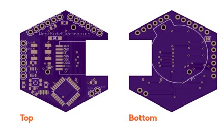
The cutout is to ensure that there is no material under the antenna of the radio

Because I did not want to have to support two levels of power on my board, so I decided to use the 3.3V Arduino. Due to the lower voltage, I had to clock it at 8Mhz.
Initial Testing
One challenge of working with boards like the Arduino Nano and Pro Mini is that they are already clocked at 16Mhz because the supply voltage is 5V. Because of the bootloader differences, I could not expect them to be a drop-in replacement on my board running at 3.3V. So I had to burn the 8Mhz, 3.3V bootloader into the chip first, before soldering it onto my board.
The problems started when I soldered on the ATMEGA328P stolen from an Arduino Nano clone. I programmed it with an Arduino ISP, and flashed the 8Mhz, 3.3V Arduino Mini Pro bootloader through the ISCP header. The LED on the Nano started to blink faster, and there was no smoke, so I assumed that all was well. However, when it was on the PCB, I was not able to communicate with it, with either an CP2104 or with the Arduino ISP.
When I resoldered it back onto the Nano, it started to work again. I attempted to debug the main PCB, but it was almost identical to the Nano, and I could not find a significant difference or problem.
So back to the drawing board, but this time, I eliminated everything that was extraneous to getting the ATMEGA328P to work and came up with this beauty, with all its debugging pins broken out.
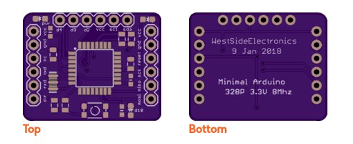
Minimal Board
In which I am a fool
Turns out that I forgot to switch around the RX and TX lines on the CP2104 communication module, leading to a lot of self-doubt and frustration.
The minimal module works at 8Mhz beautifully.
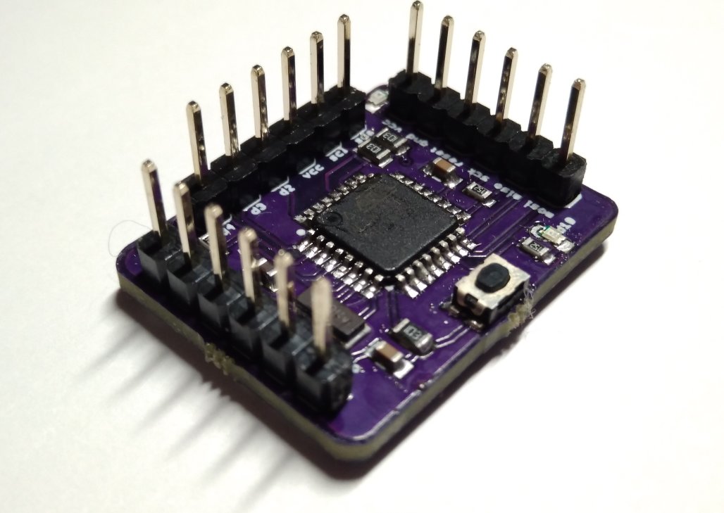
The minimal board rips out everything that isn't required to run Arduino, leaving only a reset button, one power LED, user LED, and one data LED for the SCK line. All major communication lines are broken out including the I2C and SPI lines, along with a few digital pins.
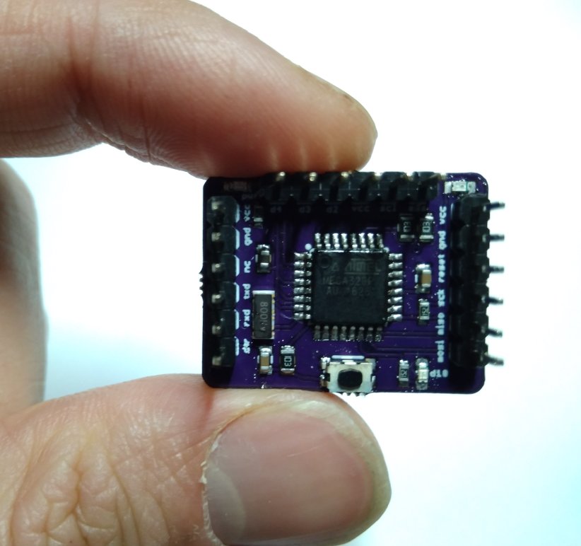
Look at how cute it is!
Now that I know this design works, I can port it forward to the actual design.
A collection of help links
http://arduino-info.wikispaces.com/Nrf24L01-2.4GHz-HowTo