A More Precise ADC
Measuring voltages in micro volts!

Why is this project cool?
Measure tiny voltages! Without a lab bench! Set up a Wheatstone bridge! The proper question is, why isn't it cool?
Motivation
Wheatstone bridges are finicky little things. But they are very useful because they transform problems. Inherent to many objects is a resistance, and often, this depends on a thing that we want to measure, such as temperature and strain. However, the problem is that these changes in resistances are very small, and measuring them directly is not practical, because large currents would be required to have an appreciable change in voltage.
A Wheatstone bridge converts the problem of measuring resistance to measuring voltages.
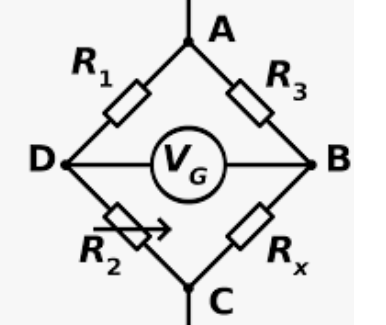
Let's say that $R_x$ is the resistance that we want to measure. Here, if we set up the bridge such that $R_1 = R_3$, then we just want to adjust the resistance of a known variable resistor such as $R_2$ so that $V_G$ reads 0V, and then we would know that the voltages across D and B are perfectly balanced and we can just read off the resistance of $R_2$. By varying the ratio between $R_1$ and $R_3$, $R_2$ can be used to get very precise resistances of $R_x$.
However, the current tools that I have are not accurate enough for me to make such a measurement, and I often have to rely on a laboratory multimeter to calibrate my circuits. The ADC on most chips only go up to 12bits, which is approximately has the resolution of 1mV, not early enough to get an accurate sense of the zero point.
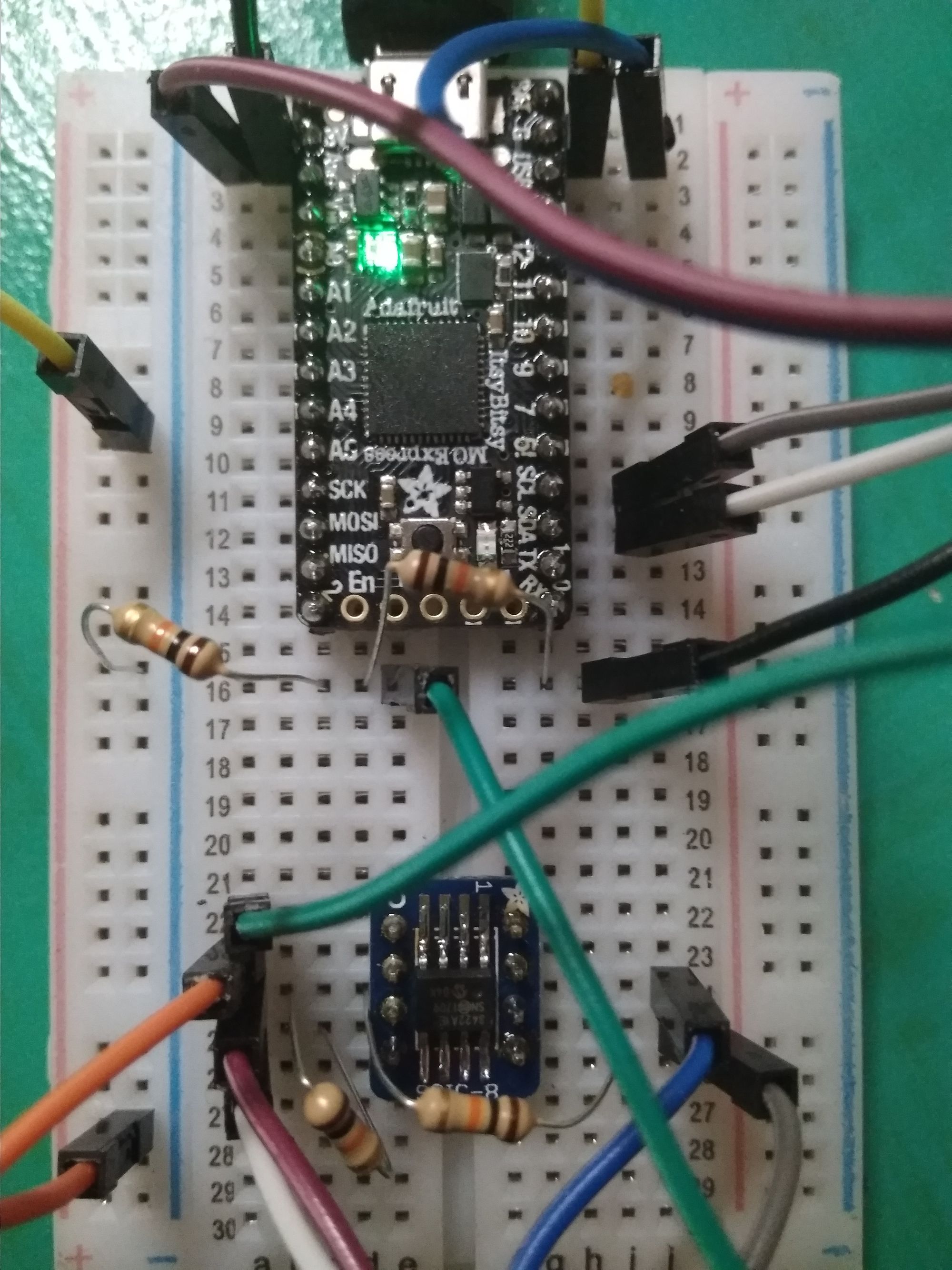
For my project I decided to use the MCP3422, a 18 bit, two channel ADC and the Itsy Bitsy M0 Express running CircuitPython from Adafruit.
I2C
In order to talk to the MCP3422, I had to use I2C.
I2C stands for Inter-Integrated Circuit , and it is a protocol that is used to talk to sensors and other microcontrollers. One serious advantage is that all devices on the I2C bus share the same bus, so the number of connections remains constant even as the number of devices grow.
However, because it relies on signalling to prevent collisions, sort of like when two people are talking at once over the phone, I2C has always been a little more complicated than other protocols to implement, requiring a precise and set way of indicating that information is being sent across a common bus.
Getting I2C working is always a pain, and I was pleasantly surprised that then, with CircuitPython from Adafruit, it was very painless. I came in with the full knowledge that I was going to have to read a lot of documentation: the chip and the device itself, and the really nitty gritty details of lining up the right bits in the right order. Combing through documentation can be tedious, but it has to be done, what I'm surprised was how little time it took to set everything up.
ADC
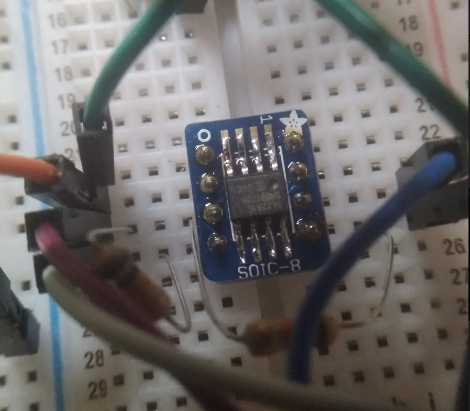
The chip in question is the MCP3422, a 8 pin DIP/SOIC that has the capability of going up to 18 bits of resolution of +/- 2.084V. The ATSAMD21 on the Itsy Bitsy M0 comes with 12 bits of resolution, although Adafruit reports it as if it were 16 bits (!!) in Circuit Python. For a range of 3.3V, this works out to a resolution of 0.8mV, and if we throw a little noise in there, it can vary up to ~5mV. This is good for most purposes, but if you were trying to build a Wheatstone bridge, that kind of error might be unacceptable.
18 bits of resolution actually works out to 17 bits if you are using the MCP3422 in one sided mode (i.e. you tie one input channel to ground). This works out to about 15.625 uV for a range up to 2.084V, or 25.177 uV for a range up to 3.3V. This might vary up to 100uV, and this is almost 50 times the resolution on a normal board. I thought 18 bits would be sufficient as getting a higher precision would require ensuring that the noise from other parts of the circuit do not interfere with the higher precision.
Note that to use a higher range, this chip would need a voltage divider before the voltage is fed into the chip. Any voltage higher than the reference would saturate the readings.
Programming
Programming and using this sensor isn't difficult. Once the I2C is working, it is just a matter of setting the configuration bits and reading the data. I did run into a problem of getting the chip to read ground at 18 bit resolution mode where it would send me 1s for the second and third data byte instead of zeros. The following is the code that I used to program the Itsy Bitsy. Two 10K pullups were used on the I2C line. I also wrote a library that is available on Github:
import board
import busio
import time

# Known problems
# Setting state  = 18 and reading ground results in maximum value output
def set_state(channel,gain,bits,continuous):
    channel_sel={1:0b00,2:0b01}
    gains_sel={1:0b00,2:0b01,4:0b10,8:0b11}
    bits_sel={12:0b00,14:0b01,16:0b10,18:0b11}
    return (0b1<<7|channel_sel[channel]<<5|continuous<<4|bits_sel[bits]<<2|gains_sel[gain])


def convert_bytearray(data,state):
    lsb = {12:1000,14:250,16:62.5,18:15.625}
    print(data)
    if state==12:
        value = ((data[0]&0b111)<<8)|data[1]
    elif state==14:
        value = ((data[0]&0b11111)<<8)|data[1]
    elif state==16:
        value = (data[0]<<8)|data[1]
    elif state==18:
        # fix a strange issue with the chip...
        if (data[1]==data[2]) and (data[1]==0xff):
            if ((data[0]&0b10)>>1) == 1:
                print("is grounded")
                value = 0
            elif ((data[0]&0b10)>>1) == 0:
                value = ((data[0]&0b1)<<16)|(data[1]<<8)|data[2]
        else:
            value = ((data[0]&0b1)<<16)|(data[1]<<8)|data[2]
    else:
        value = 0
    print("Value is: {:.3f} V".format(value*lsb[state]/(1000000)))
    print("Exact value is: {:.3f} mV".format(value*lsb[state]/1000))
    print("Exact value is: {:.3f} uV".format(value*lsb[state]))
    return value

print("start.")

i2c = busio.I2C(board.SCL, board.SDA)

while not i2c.try_lock():
    pass

# i2c complete, begin setup
# note that r/w is read when 1.
# configured for 18 bit mode
# note that the internal reference is 2.048V
# 00: 12 01: 14 10: 16 11:18
bits = 18
channel = 1
gain = 1
continuous = 1

i2c.writeto(0x69,bytes([set_state(channel,gain,bits,continuous)]),stop=False)

print("done")
result = bytearray(4)

while True:
    i2c.readfrom_into(0x69,result)
    convert_bytearray(result,bits)
    time.sleep(1)