The most useless IoT table lamp in existence
How I made the most useless IoT table lamp in existence. Now comes with mechanical and electrical design comments!


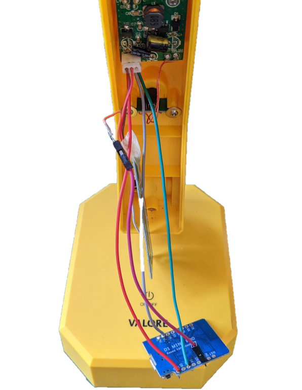
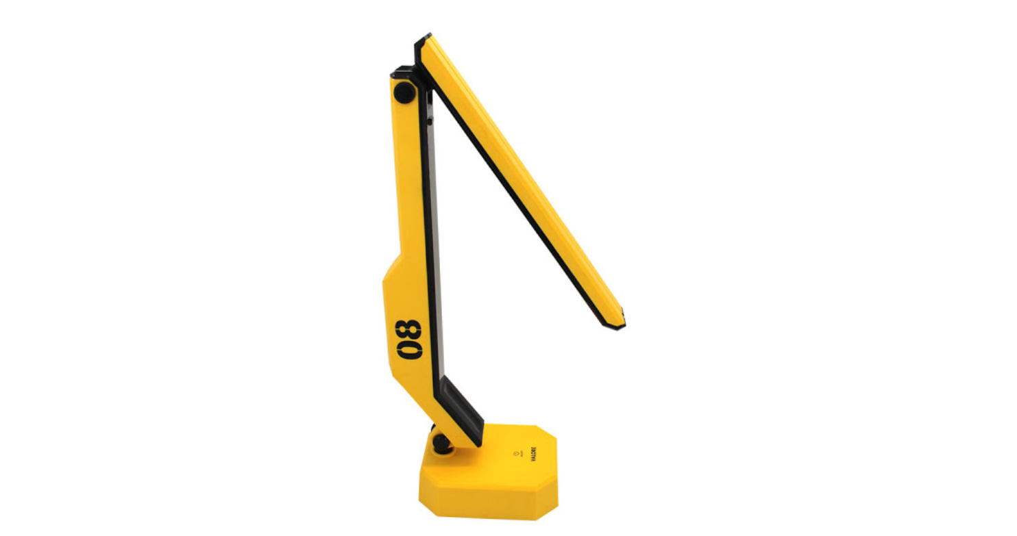
Today I want to introduce the most useless IoT thing that I've made so far. It is a table lamp that I've retrofitted with a WeMos Mini Pro.
Tldr; took me way too much effort to control the lamp wirelessly. Who needs a wireless table lamp anyway?
How this lamp is used
This table lamp is literally the most useless thing in existence:
- It is on my table. 1. Take out my phone. 2. Find the MQTT app. 3. Press the light level icon. 4. Select light level.
- It is not on my table. 1. Why isn't it on my table? 2. Why do I want to adjust the brightness of something far away without going over to it?
Compared to the original lamp WITHOUT the IoT portion stapled in:
- It is on my table. 1. Touch the light level indicator.
- It is not on my table. 1. Walk over to the device. 2. Touch the light level.
Now that I've explained how silly this lamp is, let's get into the really silly part of this: how much effort it took to add IoT to this lamp before realizing it wasn't such a great idea.
Attempt 1
Realizing that the voltage regulator (78L05) couldn't supply enough current to the ESP8266 which can draw up to 200mA when in operation, I decided to replace the voltage regulator. I happily placed an order on LCSC for a voltage regulator of the same package and promptly forgot about the whole matter. However, things didn't go planned...
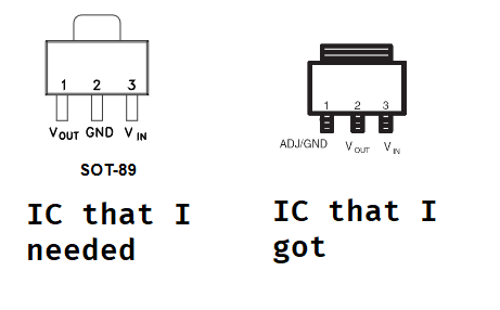
See the difference?
Notice how the GND and VOUT signals are swapped? It turns out that SOT-89 voltage regulators have a pin layout that is different from the layouts of other package sizes, and in my haste, I didn't check the pin layout.
So after scratching my head and wondering why nothing was lighting up and doing some measurements with my multimeter, I had to order another IC.
This wasn't easy because I had to go through each datasheet to make sure that they corresponded to the layout I needed, and there were only a few that met the criteria of supplying enough current, having a SOT-89 size, and having the correct pinout.
Directly soldering to the header wasn't such a good idea because it prevented me from using the original interface board. But I didn't know it at the time.
Attempt 2
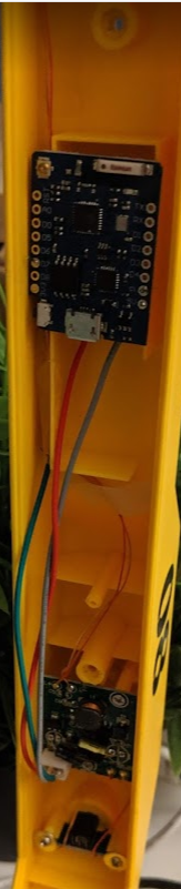
I replaced the original IC with a LDK220U33R from ST, which provides 200mA in a SOT-89 package (yay!). I also resoldered the connections from the WiFi chip to the bottom of the LED driver board so that I could plug in the original interface.
Because the PWM can only be driven by one source, the WeMos ESP8266 board will sample the PWM signal from the interface board to control the LED driver board.
I learned quickly ADC isn't a good way to measure PWM from another IC and switched to measuring pulses. I got pretty consistent results using the pulseIn function to calculate the duty cycle of the PWM. The result is rounded to the closest 10 to prevent flickering of the LED due to errors in the measurements.
MQTT Control
The WeMos IC is used to connect to the MQTT network and it waits for a command to light up the lamp.
It seems like the common way to send light/color requests over MQTT is via decimal values from the few MQTT apps that I sampled. However, since I set up my MQTT network to send hex values, I decided to map the hex values to a fixed multiple choice input that the app provided, so that I could use a few preset options to change the intensity of the light.
I personally like using hex values because it maps cleanly from 0 ~ 255 using just two characters, so you can define a 6 character string that holds all the values you need to set RGB colors with. The same range for decimal values would involve 9 characters, a 50% increase in information required.
Replacing the interface board
Unfortunately, I didn't have any luck replacing the interface board in the same manner it was installed in, even with super glue. To trigger different power settings, I would have to press really hard on the surface. Only the power button, which was not removed, could still be easily used to turn the lamp on and off.
Inside the lamp
Taking apart the lamp was a matter of a few screws and some levering with a screwdriver. I find that the cheap combo flathead + crosshead screwdrivers that they hand out at engineer-y events work pretty well for taking apart stuff. I personally use an Adafruit© Pocket Screwdriver.
Power
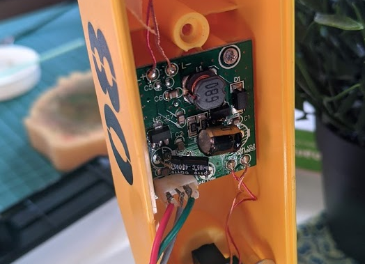
The electrical part of the lamp consists of two parts, a LED driver, and a interface board. The LED driver is directly powered by a 12V wall wart and it steps down to 9V for the LEDs. Given the components on the board, it is most likely a switching regulator for power efficiency. The inductor, the diode, and the SOT223 IC gives it away. The LED driver board also contains circuitry that connects to and powers the interface board. I found that the interface board outputs a PWM signal, so it is likely controlling the switching regulator's enable pin to control the brightness of the lights.
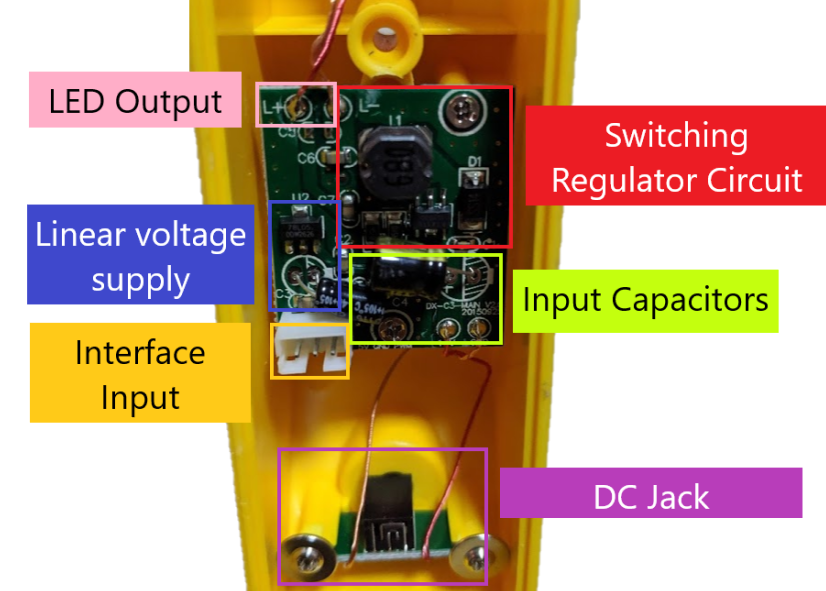
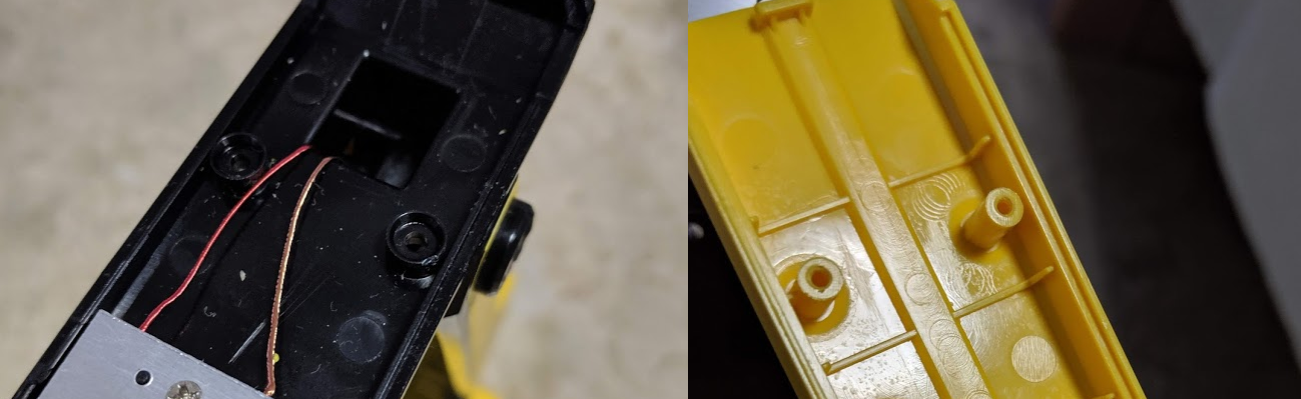
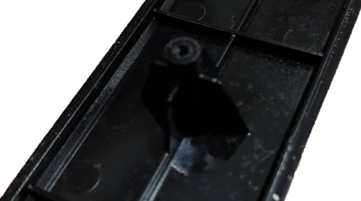
The DC jack has an interesting mounting solution that places it perpendicular to the surface of the structure. There are two posts with channels on each side, allowing the PCB to be slotted in, and it is held in place with two screws with wide heads.
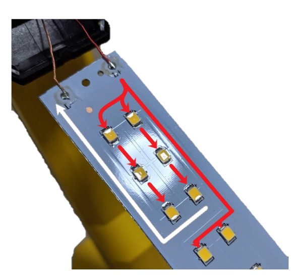
LEDs
The LEDs are connected in series using big planes of copper instead of tracks. My guess is that this is done so that the heat is spread out over the whole board and to carry a significant amount of current. There is also a backing of aluminium on the PCB to act as a heat sink.
Interface
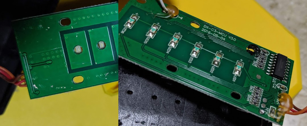
In order for the board to detect touch, it needs a capacitive plane of copper. This plane has to be as close as the surface you are touching, so you need to make that side as flat as possible. However, something still has to light up where you pressed, and the easy way to do this is to put an LED in the place you want the light.
In order to combine these two requirements, the engineers decided to drill a hole in the middle of the plane and put the LED upside down so that it would shine through, while still allowing the plane to be as close as the surface as possible. You can see it in the photo above where the bottom part of the LED is exposed. I'd imagine this would have prompted a clever way of positioning the LEDs upside down in the right place for the pick and place machine because LEDs are usually oriented upwards.
Mounting
Another interesting feature of the interface board is that the mounting holes on each side of the PCB were attached to stands that were melted to hold the PCB down without the use of any additional attachment mechanisms. I thought this was a clever way to hold the PCB securely close to the surface. You could press the PCB down with a clamp and melt the posts.
Interface IC
The interface PCB is attached to the LED driver board with a 3 pin connector, and to an additional touch surface on the base of the lamp for the on/off switch. The interface PCB outputs a PWM signal based on the state of the buttons, and it has a boot sequence where it lights up each LED sequentially.
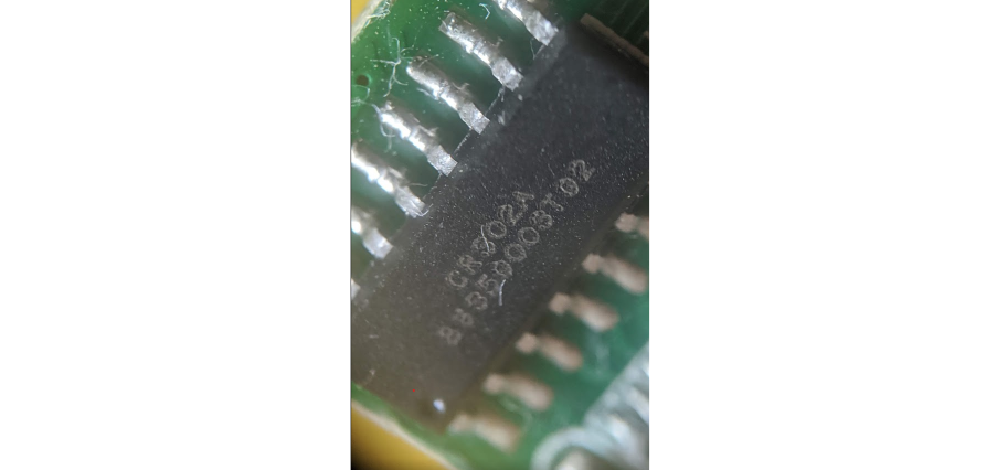
Trying to find the touch interface IC proved to be very difficult. I only found a single seller on Alibaba and no datasheet. This is likely a specialized IC made for this particular purpose. If that is true we can expect to find other touch-controlled table lamps that have 5 lighting options and an on/off button.
Mechanical Elements
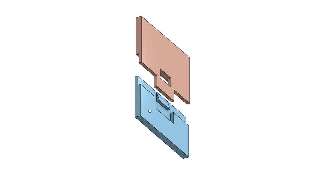
Inset Catches
If you have two posts that need to line up with each other, a good idea is to use a physical catch to align the two parts rather than trust to precision to line up the holes. This is important when you are trying to use a screw to secure the two objects together.
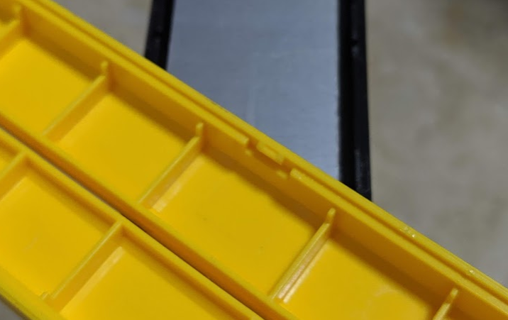
Hook and Catch
The hook and catch is an annoying design feature for me because I will inevitably break something if I'm not careful about it. It is also therefore a useful design pattern you can use to connect two parts together securely, for example, in an enclosure.
Flanges
Flanges strengthen features for comparatively little cost. Here it is used to strengthen a screw post.
Hinge
The hinge mechanism is actually quite interesting because it is a bolt and nut being used to hinge and squeeze the two yellow arms around the black hinge, using resistance to create friction and allowing the lamp to stay at the angle it was set to. The horn highlighted in red limits the motion of the lamp, preventing the user from tipping it too far backwards.
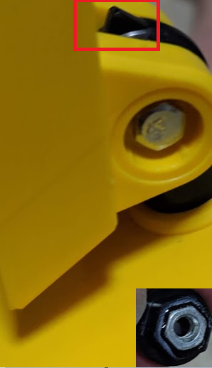
The plastic cap hiding the bolt and nut has another feature as well. It captures the bolt and nut by having a hex-shaped indentation, and has a slot on the exposed surface so that you can easily tighten the nut and bolt with a flat head screwdriver without needing to use socket head screwdriver.
Conclusion
So after all that work, I have a lamp that I can turn off and on manually, and control the intensity of the lights remotely. I guess this will be useful if I have another sensor that needs to turn on a light somewhere else, but since most of my stuff is contained to my room, I find this highly unlikely.
It was fun to know that I could retrofit a lamp with some IoT technologies, but this project goes to show that careful consideration of whether the device will benefit from IoT is important because it can be helpful in determining the viability and usefulness of the project. I.E, slapping IoT onto stuff doesn't automatically make them better.