The Headcrab Project (taking control of another circuit)

So, this week I managed to get my hands on one of these (recycled):
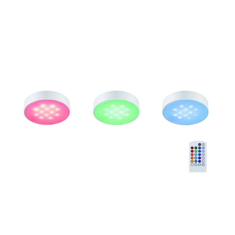
Figure 1. 3-Light LED RGB Puck Light Kit
This is sold in Home Depot for about $30. However, the one that I salvaged did not have the remote, so I was unable to switch it on. I tried an IR remote that I had, just on the off-chance that they shared the same protocol, but no luck. Going off on a tangent here, I feel that Arduino starter kits are amazing for spare parts, but not so fun if you are learning Arduino.
Back to our project, off with the cover!
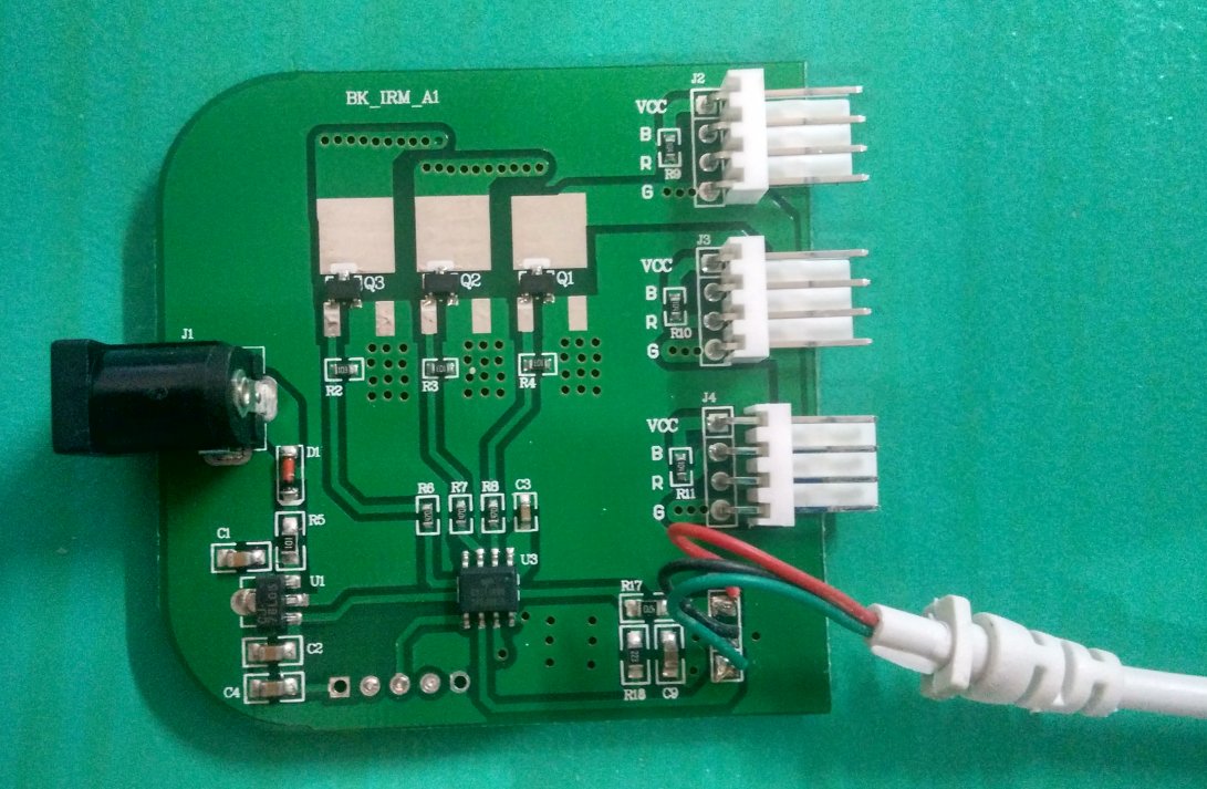
Figure 2. Inside of the controller
Tracing the leads of the chip led me to conclude that this was a fairly standard circuit to power an analog RGB light. The way that it works is that the light is provided some voltage (12V), and it has three sinks to ground through a red, green, and blue LED. The more current that an LED is allowed to sink, the brighter it is. The microcontroller opens the 'gate' for each sink, thereby controlling the current through each RGB LED and hence the perceived color and brightness.
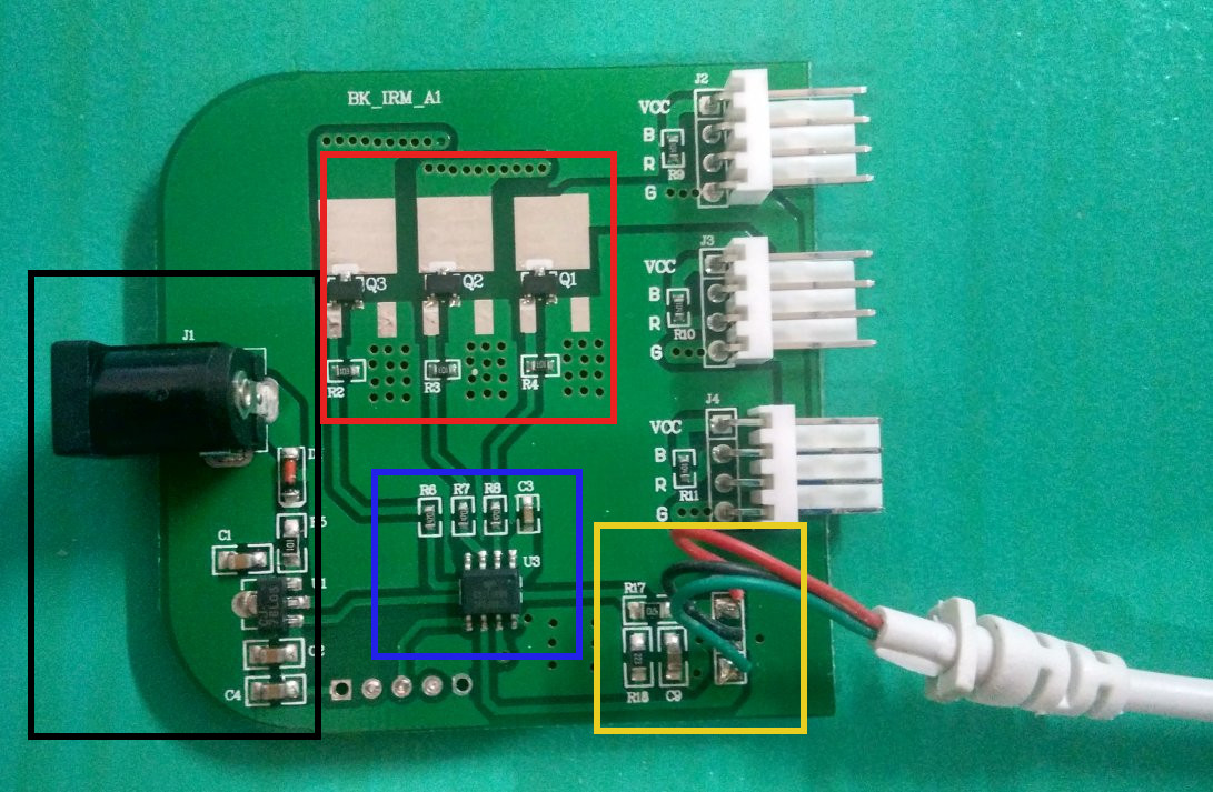
Figure 3. Controller Details
The red box are the MOSFETs (transistors) that control how much current to sink. We cannot use a chip to sink the current because LEDs can draw a large amount of current which might cause the chip to fry.
The black box is the power circuitry. It takes in 12V and it has a step down voltage regulator to 5V, which powers the chip and the IR receiver.
The blue box is the chip that controls this circuit. Because it had three similar looking circuits leading from R6, R7, and R8, this led me to conclude that these were the leads that controlled the MOSFETs (aka the switches for the current sink). A capacitor C3 to ground indicated that the pad might be a power line.
Finally the yellow box is the IR circuitry. The nice thing about this part is that it exposes the ground, signal, and power leads, making it easy to tap into.

I was hoping to replace the on-board chip directly with an Attiny85 chip but it turned out the footprints and the pinouts of the two chips didn't match. I could not determine what chip was on the board, or what protocol for the IR receiver was programmed into the chip, so I desoldered it.
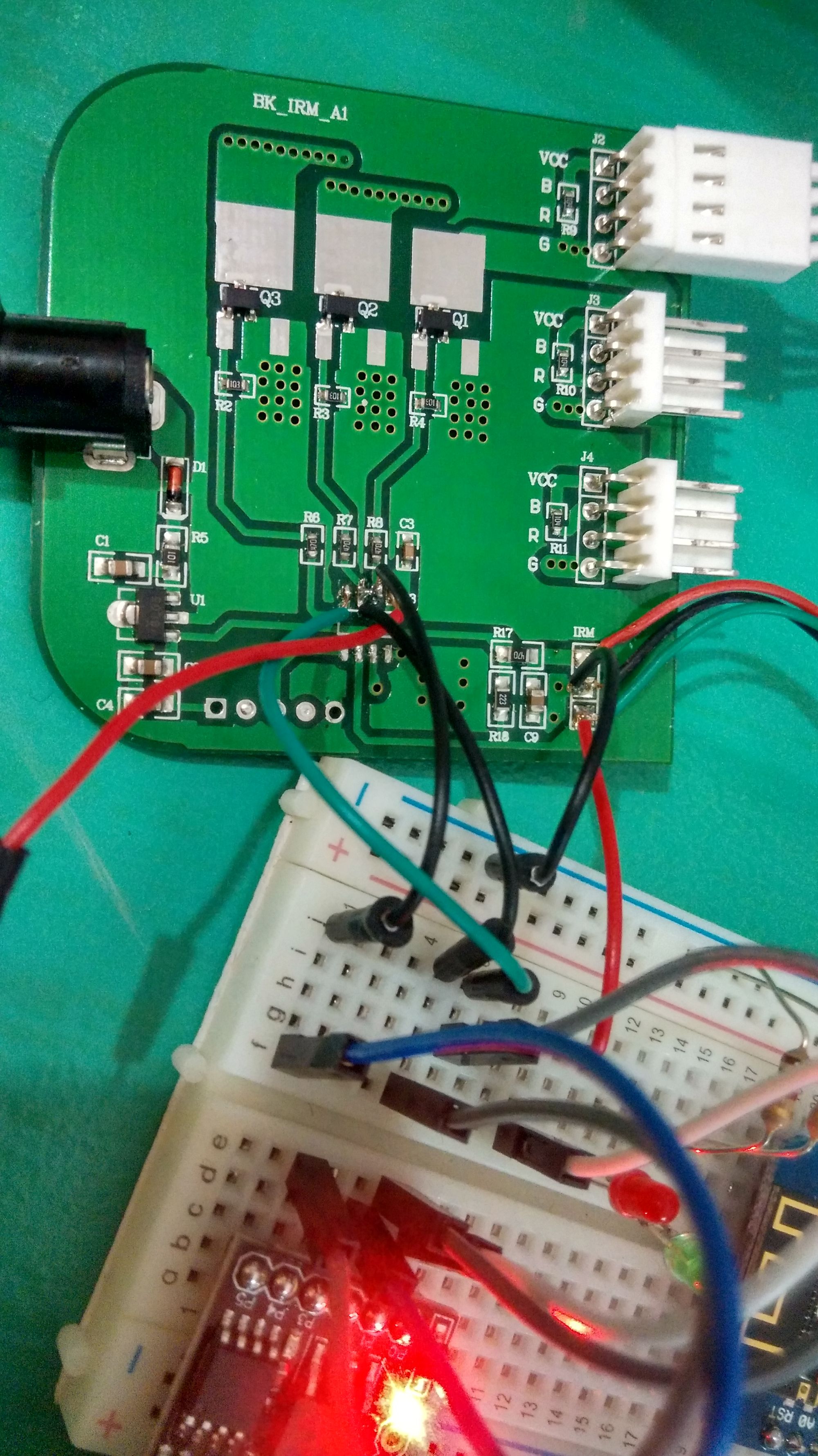
I attached my own chip via some wires, aka: headcrabbing the board, with reference to the iconic creature in Half-Life.
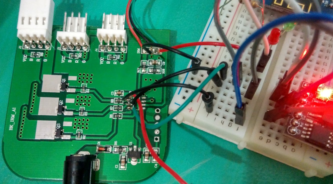
Figure 4. Headcrabbed circuit
The problem that I had with the Attiny85 was that it only had two PWM output channels and one of them was required for the IR sensor so that it can detect and interpret the incoming signals. However, you cannot control the RGB signals independently if you only have one PWM channel.
Luckily, there is the TinySoftPwm library that Digistump provided. However I had to dig into the code to comment out a line enabling it for Pin 1 (P0 on board) because that was reserved for the IR library. After determining the type of signal that I was sending with the remote, I also removed additional .cpp files from the IR library because they just increased the size of the final file. This reduced the size far enough such that I was able to upload it to the Attiny85.
Figure 5. Working RGB lights with IR remote
This shows that I am able to control this circuit with a programmable IR remote. The cool thing is that I can now program various modes or tie it to a network, and hence expanding the capabilities of this cabinet RGB tap light greatly.
This project would not have been possible without the IR and Digistump libraries. This project roughly took me about 5 hours to do. It would have been easier if I just plugged it into an arduino, but that would have removed most of the challenge and fun of this project.