The Essentials Board
A universal breakout board that takes care of power and clock for SMD microcontrollers.


What is it?
A universal breakout board for QFN and TQFP chips with integrated clock and power lines. Once this board is set up, the only things you have to breadboard are two wires: power and ground. When you remove the board, you take all the capacitor and clock connections with you.
Why is it cool?
- Less waste! When you want to use the breadboard for something else, instead of throwing away the random bits of wire and capacitors, you take it with you when you remove the breakout board from the circuit.
- Easier setups! You don't have to dig through the datasheet to figure out which pin has to be grounded and which has to be powered. Once you do it, it is set, so you can easily continue a project if you remove a board from a breadboard.
The problem
I like to try out new chips. Sampling chips is a great way for me to explore new chips and test their capabilities.
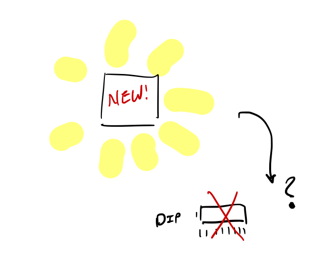
However, they don't always come in DIP formats. Almost no one produces new microcontrollers in DIP formats today, so it is not easy to test out new chips.
One way is to produce a PCB to mount them, and because each IC is different, a new layout needs to be generated each time I want to test a new chip. This is mildly annoying at the very least and adds up the cost quickly. It is also quite wasteful, because I usually use 1 PCB of the lot of 10 that is the minimum order amount from most PCB fab houses.
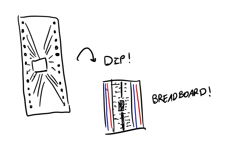
So in order to reuse the board for different microcontrollers, another way would be to just use a generic layout and have the pin be broken out into a convenient DIP format so that we can plug it into a breadboard! Problem solved right? Not quite.
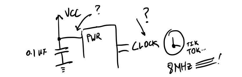
In order for the chips to run, they need power as well as a external crystal. Chips have internal clocks, but they can be quite inaccurate, and the drift can be as high as 10%, as compared to the 0.5% of an external crystal. This is especially important for timing-sensitive operations like USB and UART. The voltage supplied to each power pin on the chip has to be accompanied by a capacitor to ensure that the voltage remains stable.
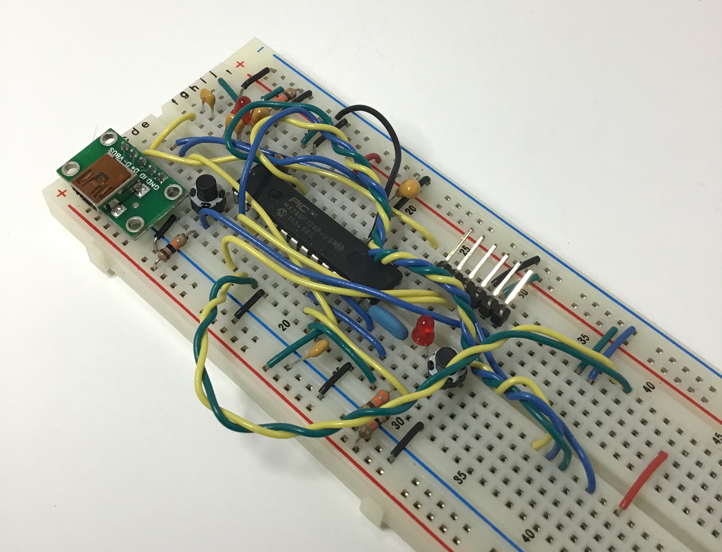
I have breadboarded circuits for microcontrollers that worked quite well even for UART and USB. However, this method creates a rat's nest of wires, which makes transporting boards a delicate affair. Removing the microcontroller from the board is also an issue, because now the wires that are left behind are just a random jumble, and more often than not, are tossed to languish in a cabinet somewhere.
The Solution
My solution to the problem of providing power and clock is to integrate it onto a breakout board!
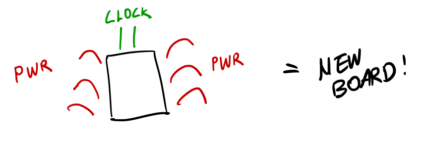
It provides filtered power on the output pins and a choice of two clocks: a 32.678kHz clock for RTC, and a faster 8Mhz clock for the core.
I initially only included these two items and had the power supplied externally, but this means that I would need to find a power source, so instead, I opted to supply power directly from the Essentials board from USB, since that is the easiest way to obtain a relatively stable voltage supply. I decided to use a CP2102N IC as the voltage regulator, and it additionally provides UART-USB communications, which could help in debugging.
Potential issues
There are a few potential issues with such a setup however. There is a reason why datasheets specify capacitors should be placed as close as possible to the input pin. The further the capacitor is from a pin, the smaller the effect it has on smoothing the voltage. Connecting the Essentials board to a breakout necessarily is further than mounting the capacitor on the board itself. The same goes for the crystals, and I'm not sure how well it will perform given that it might be some distance away from the input pins.
The benefit of this design is that all components are mounted, so breadboarding a design and removing it won't create a ton of waste from all the capacitors thrown into the bottom of the toolbox, never to be seen again... However, there will still be random wires jumping from the essentials board to the breakout board.
Impressions
This board was less helpful than I expected to be. I still had to cut and wire the connections from the essentials board to the breakout board. The main benefit would be that the essentials board is compatible with breakout boards from other companies like Adafruit.
The Essentials Breakout Board
I call this board The Essentials Breakout. It provides a common power and ground pin, and power and ground can be applied to any pin using a jumper. The same can be done for the clock, although jumper wires will be required. You can only make it so modular on for a board of a fixed size.
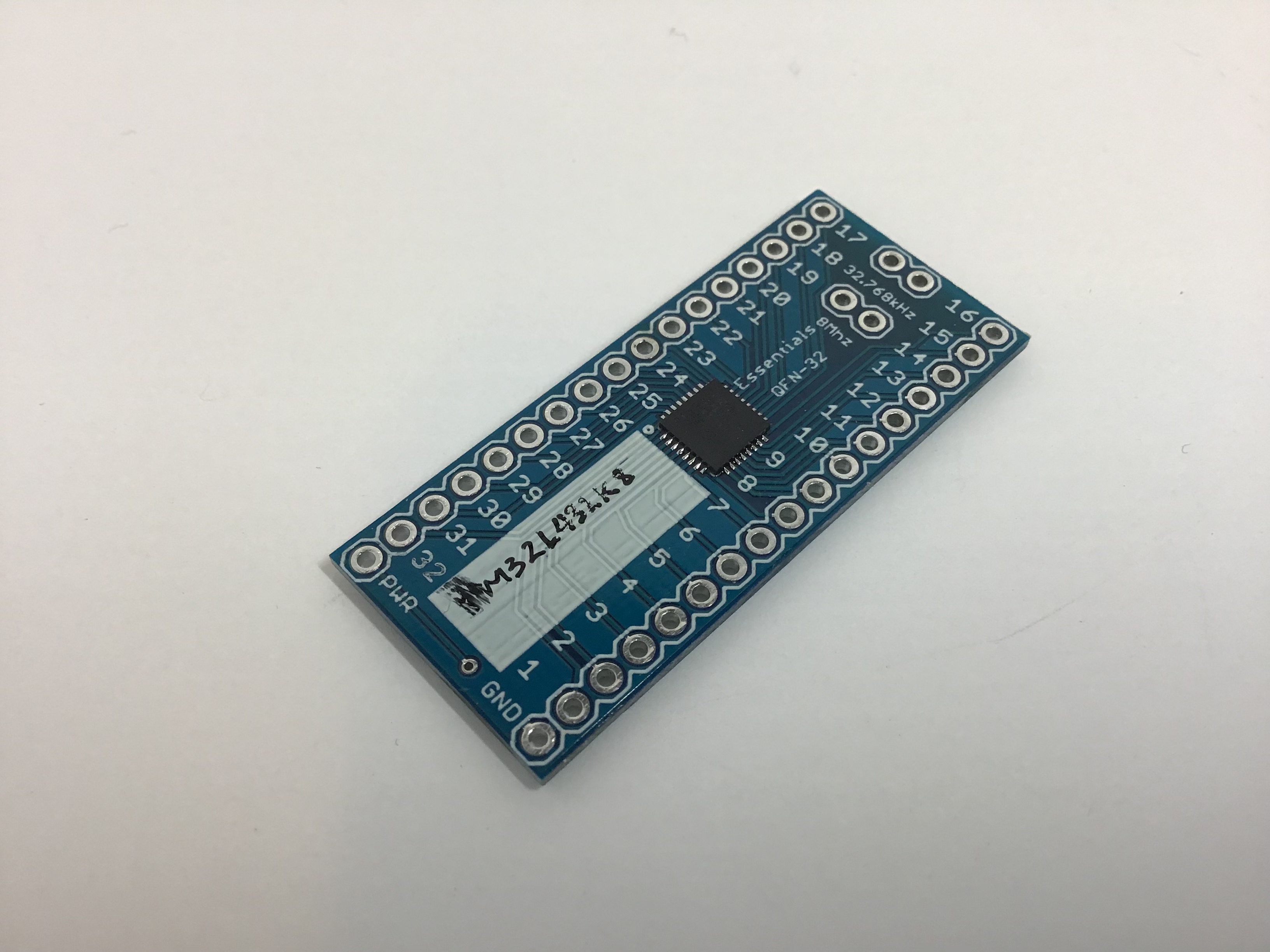
I thought I would have to make the board wider, but when I placed the components, I found that I could squeeze in all the components without increasing the size of the breakout board. While the board is definitely wider than a DIP-24, it does include capacitors on the power lines as well as integrated crystals and their load capacitors.
Grounding pins is done by soldering a 0 ohm resistor on the 0603 pad and not soldering the jumper.
I find that I really like this alternative design, because it reduces the amount of flying wires and you only need two wires: power and ground, which makes this a really compact solution.
Impressions
I received the boards and I immediately started soldering on the parts. It requires some time for the initial setup, and it took me about a half hour to get all the components soldered on. However once on, I would have a permanent minimal system that I could easily move around instead of being fixed on the breadboard.
The coolest thing was that I was able to switch to a completely different chip and repeat the same process on the same board, saving both time and money.
Improvements
I switched out the solder pads for 0603 footprints. This would add an additional option for the pin to be pulled up. The thermal pad below the QFN chip was further improved by using a NC (normally closed) jumper to ground so that the base of the QFN can be left floating if desired.
Conclusion
While this is a really simple design, I think it is a winner in terms of time saved for prototyping, plus the convenience of having the entire system on a single board really wins out.