Harnessing solar for sensors 🌞
Proving power to wireless devices from the sun. INFINITE ENERGY!

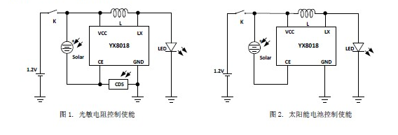
While conducting the fairy light teardown, I came across the YX8018 IC which was seen in many other teardowns regarding garden lights. These are small stakes with a solar panel. You stick them in the soil and they light up at night.

It costs $0.08 per IC, and it is a simplified joule thief circuit that requires only an inductor to work. This IC is also readily available, as compared to the one I found in the fairy light circuit, which I couldn't get a hold of.
Naturally curious, I had to give building this circuit a go.
The Zeroth Law
I didn't want to buy a garden light stake as I don't have a garden that I could conceivably use it in, and there is no guarantee that they would use this IC for me to play with, therefore I decided to breadboard my own circuit.
Side note: Having components on hand is tremendously useful when it comes to prototyping. It saves on time required to look for these components, to buy them, and to look up the relevant information. In my case all I had to do was to buy a set of inductors.
I used lots of parts from this kit: Northwestern ME 233. I advise against getting a "Arduino Kit" because they contain a bunch of assorted components that don't really play very well together. Instead, a set of generic parts that can be used in any project is a better investment.
| Component | Comments |
|---|---|
| Resistors | Get a pack of 1/4W through-hole resistors, 500 count |
| Capacitors | Get a pack of through-hole capacitors, 200 count |
| Inductors | Get a pack of 200 count |
| Transistors | Get an assorted pack of NPN and PNP |
| Diodes | Get a pack of about 20 |
Associated with having these components is keeping track of them. There is no point having all the components if you don't know where they are. Having a spreadsheet and labelled packets goes a long way in tracking what you have and what you don't.
Just add components
Being lazy, I thought I could get away with a cheap voltage boost regulator and not have to modify the default circuit by a whole lot.
The default circuit produces voltage at 1.6V, just enough to light an LED. I thought I could replace the LED in the circuit with a simple voltage boost regulator to power a 3.3V circuit and call it a day.
Unfortunately, I used a AAA rechargeable battery as the backup power, which provides about 1.2V. On the seller's website, this was provided:
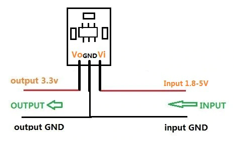
The step up regulator required 1.8V minimum. So there was not nearly enough voltage from the battery alone. That was quite disappointing. But I figured if I had 2V from the solar panel, that could at least provide 3.3V while the sun was up. Not ideal, I know, but it would at least prove this unit was working, and I could figure out the battery issue later (boost it up to 2V then boost it to 3.3V? 😂).
Nope. Not even close. The voltage regulator gave a solid 2.5V when the output from the solar panel was 1.9V. A rock solid 2.5V, but not nearly what I needed.
Easy 7 step process to a cleaner 3.3V
To boost the output from the YX8018 and create a usable output voltage, I made a DC voltage rectifier to replace the boost IC that I bought. Feedback is also added to regulate the voltage to 3.3V.
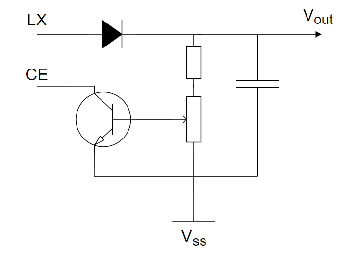
CE controls the output LX on the YX8018. LX is a 200kHz pulsed output at 1.5V. When CE goes to ground, it turns off LX. The connection to ground for the CE pin is regulated by the potential divider circuit which supplies the voltage to turn off/on the transistor.
- As time passes, the voltage along the V$_{\text{out}}$ line increases as the capacitor is charged.
- The voltage of the whole potential divider circuit is raised, which raises the voltage seen by the transistor.
- Once it passes a threshold, the transistor is closed and CE shorts to ground.
- LX is turned off, which stops charging the capacitor.
- Voltage along the V$_{\text{out}}$ line drops as the capacitor discharges.
- Voltage across the potential divider circuit lowers enough so that the transistor turns off.
- CE would start to float again, and LX turns on.
This process keeps the V$_{\text{out}}$ line at a fixed voltage, by adjusting the potentiometer, we can set the output voltage on the V$_{\text{out}}$ line to a desired level.
So with this simple circuit, we managed to create a 3.3V output voltage. Not bad!
From theory to practice
For my circuit, I used a 22uH inductor across the pins, as well as quite a number of capacitors on the output to stabilize the voltage. This is required because the circuit isn't able to source current quickly, and a large demand for current will cause the voltage to drop, causing a potential brown-out.
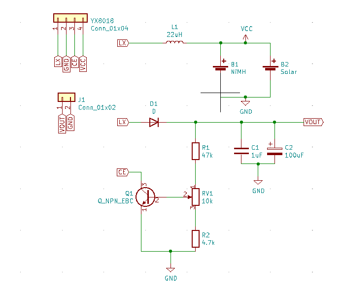
The battery used is a Ni-MH. This has several benefits over other forms of batteries: it is amenable to trickle charging via the solar panel, which lithium batteries are not, and it has a smaller memory effect as compared to Ni-Cd batteries.
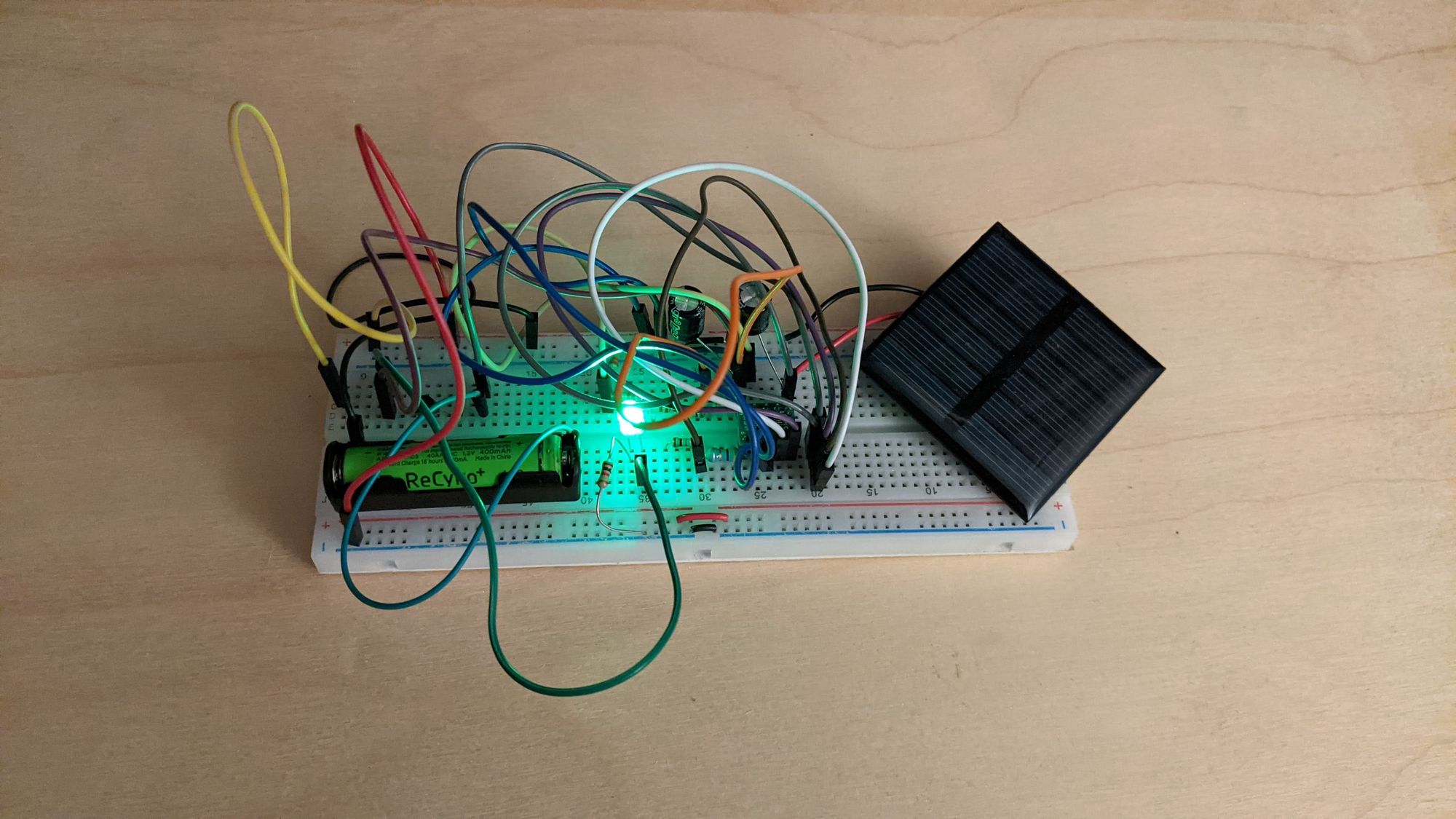
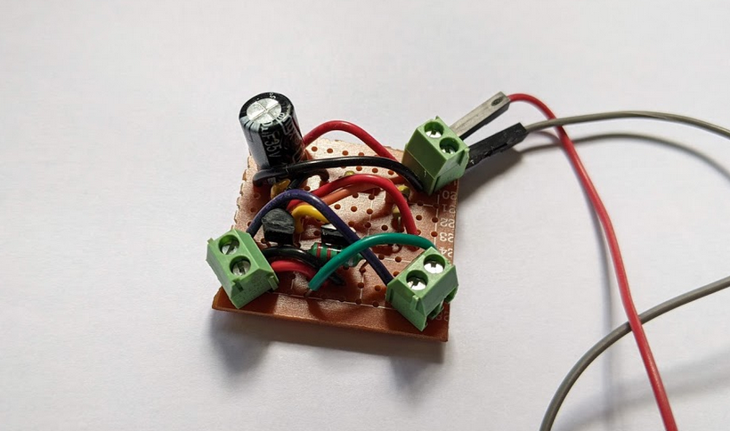
I prototyped the circuit on a protoboard and it was quite messy.
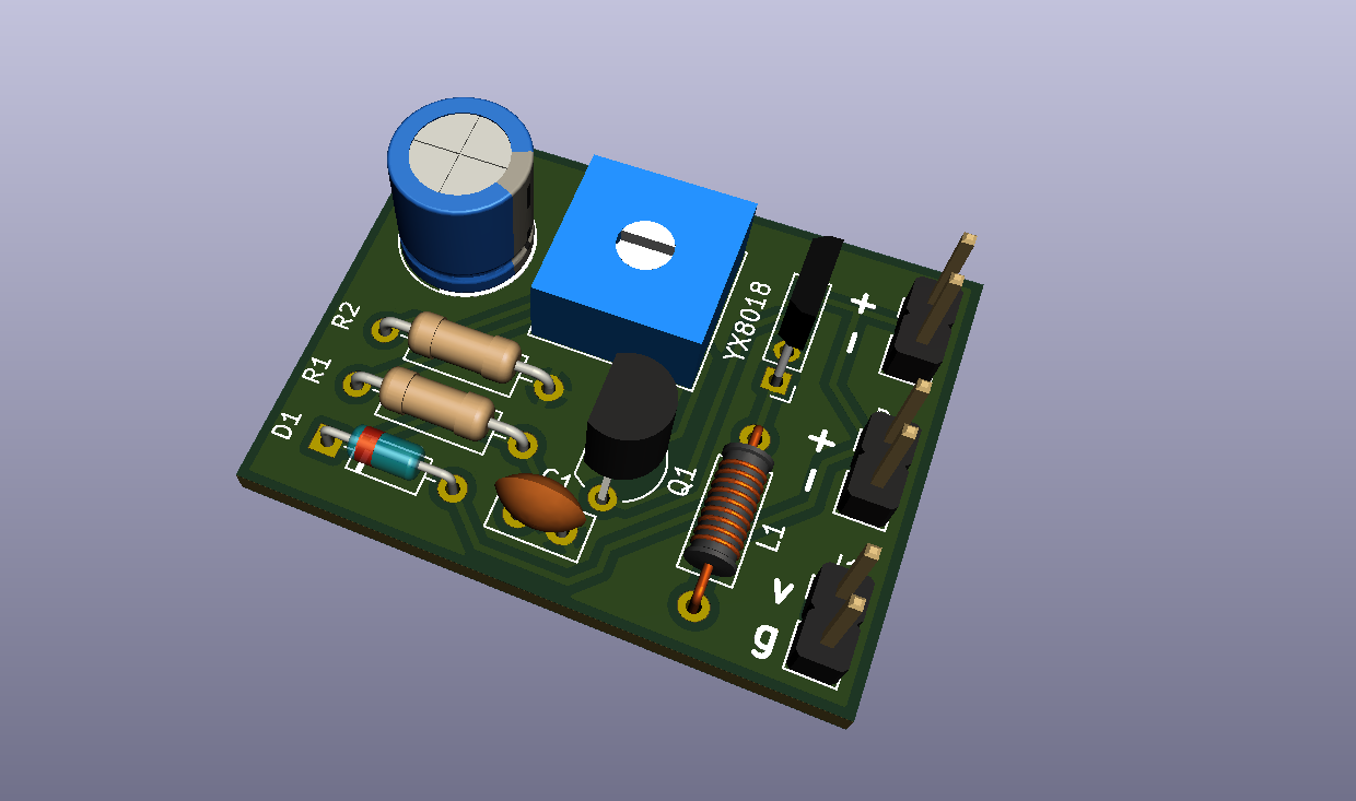
So I redid it in KiCAD and visually it looks much better.
I tested viability of the output and charging process and I found that the problem with this circuit is that the current draw is unacceptably high. With everything disconnected and the solar panel under full light, the current draw from the board is 1.04mA. I'm currently using a 400mAh battery, which gives me around 300h (if we are being conservative) of use, which is roughly 12 days if there is no sunlight.
I also found that the boost circuit in the YX4014 only activates when the light is dim. This makes sense - turn off the LEDs when it is daylight. But I wanted to control the output under any condition, not turn off the power when there is daylight detected.
Iteration two
This is quite good, but we can do better. Since the battery is directly connected to the solar cell, we can replace the entire fairy light circuit with a low-voltage boost circuit.
One problem is that most boost ICs go only as low as 1.8V, which is too high considering that we are only using 1 NiMH battery, which goes up to 1.3V.
I considered using the TPS61201DRC from TI, which grabs input voltage from as low as 0.3V and outputs a respectable 3.3V. The benefit of this chip is that the quiescent current is about 55$\mu$A. Much less than the improvised circuit we have now. The downside is that it is about \$4, which is pretty expensive. Another point is that it is a little over-specced. We should never hit 0.3V on the NiMH unless something has gone very wrong.
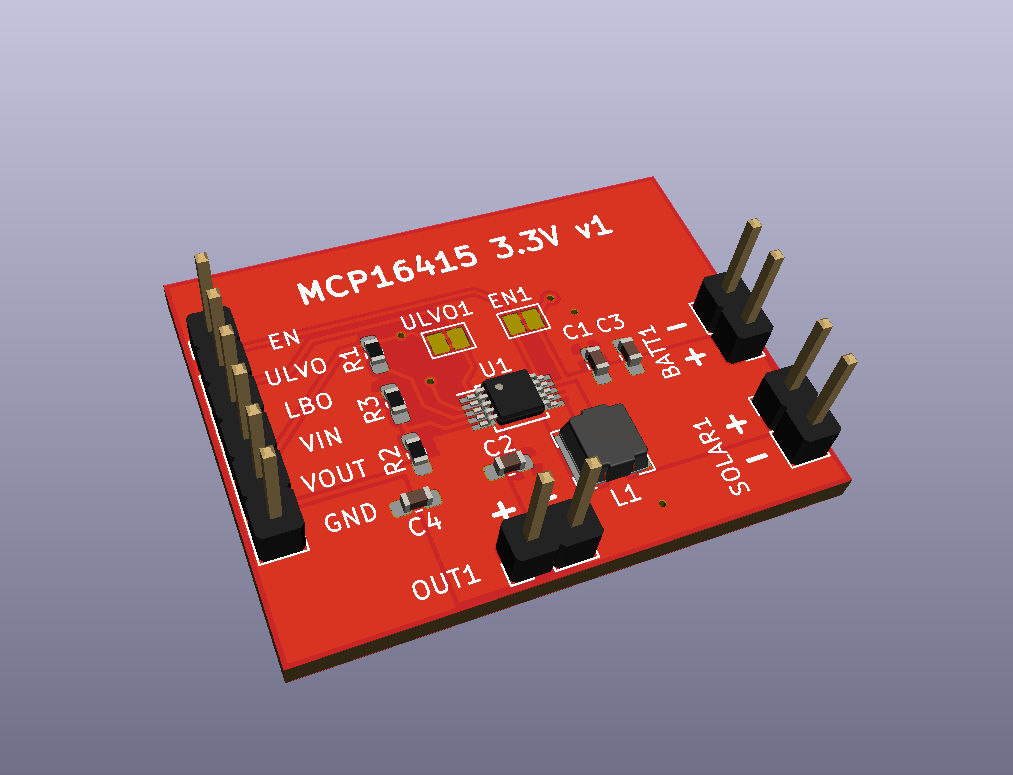
The low-voltage boost IC that I eventually decided to use was MCP16415 from Microchip. It boosts voltage from 0.8V, which is not quite as low as the IC from TI, but this is as low as we want to get anyway. The IC also has a variable output from 1.8V to 5.5V. It costs \$1.4, and has a quiescent current of 5$\mu$A when active. Another benefit is that it is slightly easier to solder.
| Property | MCP16145 | TPS61201DRC |
|---|---|---|
| Quiescent Current (uA) | 5 | 55 |
| Voltage In (V) | 0.8 | 0.3 |
| Cost ($) | 1.4 | 4 |
| Package | MSOP | QFN |
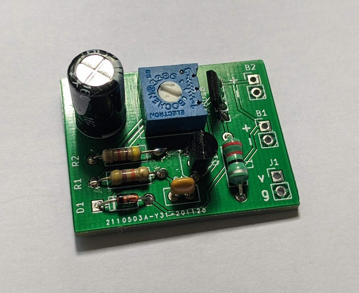
After testing the circuit on a breadboard, I designed it in KiCAD and sent it off to be manufactured!
Actual testing showed that it drew about 0.20mA to charge the capacitors and fell to 0.07mA to maintain the voltage. This is a 10x improvement over the original circuit.
The NiMH Battery
The reason why I've not added any charging electronics, MPPT etc... to charging the battery is because the NiMH is trickle charged by the solar panel. Since the solar panel is only able to provide a few mA of current at best, that is sufficient to keep the battery topped off while maintaining the battery's health without additional circuitry.
The resistance of the solar panel is 100k$\ohm$ when it is dark. Given that the battery outputs 1.2V, this means a current loss of 0.012mA in the worst case estimate.
The worst battery I have is a 400mAh, and assuming maximum losses and a buffer, the power draw is 0.1mA, which results in 4000 hours of usage (assuming no solar charging). That approximately 150 days on a single battery. That's almost a 10x improvement from our previous circuit!
Conclusion
This was a pretty successful exploration of getting an independently powered device to work without having to plug it in. The only concern with this device is the power budget, but honestly, I like that constraint because it forces me to be creative about how and when I should send and collect data.
Outtakes
One thing that really baffled me during testing was that despite these calculations and measurements, when I tested with a fully charged battery, it would deplete in a day. This really confused me and I rebuilt the circuit a few times to try to get to the root of the issue. It kept happening until I decided to measure the current draw from the battery, and it was an astonishing 50mA!
I realized that I left a probe wire to the nScope plugged in, and without powering on the nScope, this voltage on one of the pins was powering part of the nScope and ate my batteries. When I removed the probe wire, the current dropped back to the 0.07mA range.