Reverse Engineering IoT: Firmware Extraction
Doing it the 'hard' way. Firmware extraction. U-boot shenanigans. Band-aid patching. Oh my!

I have come a full circle back to IoT products and security testing. Since my original skills were in IoT engineering, I wondered what kind of security bugs could be found in devices.
Security testing for IoT devices differs from normal web or cloud security testing because there is a big emphasis binary blobs. Even getting your hands on the firmware is also not guaranteed. More often than not, devices receive their last update before they exit the factory.
Terrible from a practical security standpoint, but valuable from a vulnerability analysis learning point of view.
The device I've decided to test is a MOWE Smart Home Camera. These types of cameras are now quite ubiquitous, and you can see the same form factor replicated under different brand names.

This device can be operated and used through your smartphone through Tuya Cloud. No software update option is provided, and so to obtain the firmware requires some poking around the hardware.
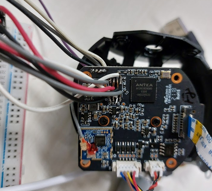
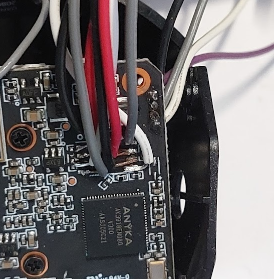
Opening the device
The UART port is identified by a 3 pin or 4 pin header on the PCB. Sometimes the TX and RX pins are not connected directly to the microcontroller as there may be a low resistance resistor inline with the signal to prevent current surges from damaging the pin. However, the resistors also prevent a continuity test from establishing a link between the header and the output pin on the IC, so it is worth tracing the path to check if there are any such resistors.
The baud rate was guesswork without breaking out more sophisticated tools. But from my experience, some good guesses for UART baud rates are 9600 baud or 115200 baud. Plugging it into my USB-TTL device yielded the following:
U-Boot 2013.10.0-AK_V3.0.07 (Jan 22 2021 - 14:16:01)
DRAM: 64 MiB
8 MiB
ANYKA SDHC/MMC4.0: 0
PPS:Jan 22 2021 14:16:03 anyka_c3: 0
magic err
magic err
command:setenv bootargs mem=64M console=ttySAK0,115200n8 loglevel=10 mtdparts=spi0.0:256k(bld),64k(env),64k(enc),64k(sysflg),3m(sys),4032k(app),640k(cfg) ppsAppParts=5 ip=192.168.1.99:::255.255.255.0 eth=00:55:7b:b5:7d:f7
## Booting kernel from Legacy Image at 81c08000 ...
Image Name: Linux-3.4.35
Image Type: ARM Linux Kernel Image (uncompressed)
Data Size: 2796904 Bytes = 2.7 MiB
Load Address: 81c08000
Entry Point: 81c08040
Verifying Checksum ... OK
XIP Kernel Image ... OK
Starting kernel ...
Uncompressing Linux... done, booting the kernel.
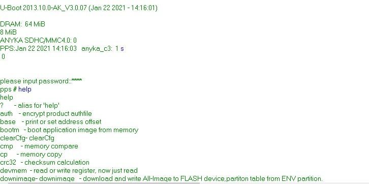
Anyka Linux Kernel Version: 1.1.12Unfortunately, because the UART only provides debug output, we are unable to proceed purely using the UART port. However, it provides a ton of useful output that we can use to further our explorations later. Notice that there is the possibility of triggering the U-Boot console, unfortunately it is protected by a password.
U-Boot 2013.10.0-AK_V3.0.07 (Jan 22 2021 - 14:16:01)

DRAM:  64 MiB
8 MiB
ANYKA SDHC/MMC4.0: 0
PPS:Jan 22 2021 14:16:03   anyka_c3:  2 5343 0


please input password::*****
password  err
resetting ...
heartbeat = 1


U-Boot 2013.10.0-AK_V3.0.07 (Jan 22 2021 - 14:16:01)

DRAM:  64 MiB
8 MiB
ANYKA SDHC/MMC4.0: 0
PPS:Jan 22 2021 14:16:03   anyka_c3:  2 123 0


please input password::****
password  err
resetting ...
heartbeat = 1
Time to bring out the big gun(s)
Extracting the SPI memory IC is a relatively straightforward affair. Since the memory was handily exposed on the IC and is a SOP-8 chip, all the leads were nice and exposed. Some quick work with the hot air gun later and the IC was out.
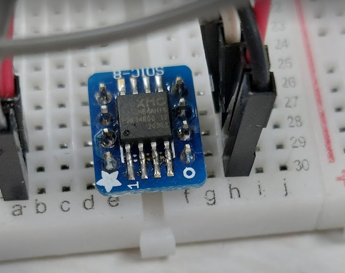
I opted to solder it to a breakout board as I did not have a SOP-8 socket on hand.
I was a bit leery of running SPI over jumper wires, but I was able to successfully extract the firmware using a Raspberry Pi by connecting it to the SPI pins and enabling SPI in raspi-config.
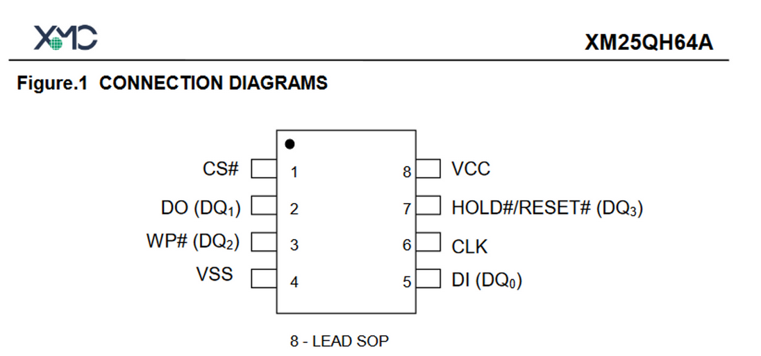
| SPI Memory | RPI GPIO | RPI Pin |
|---|---|---|
| CS# | SPI0 CE0 (GPIO 8) | 24 |
| DO | SPI0 MISO (GPIO 9) | 21 |
| WP# | 3V3 | 1 |
| VSS | GND | 6 |
| DI | SPI0 MOSI (GPIO 10) | 19 |
| CLK | SPI0 CLK (GPIO 11) | 23 |
| HOLD | 3V3 | 1 |
| VCC | 3V3 | 1 |
sudo flashrom -p linux_spi:dev=/dev/devspi0.0 -r firmware.binI used multiple dumps of the firmware with an md5sum to ensure that the firmware was not corrupted before transferring it to my laptop for analysis.
md5sum firmware_dump.binRunning binwalk resulted in some mangled output. Based off the UART output, I expected the binary file to start with U-Boot image, but instead all binwalk was able to recognise were some strings before the kernel image.
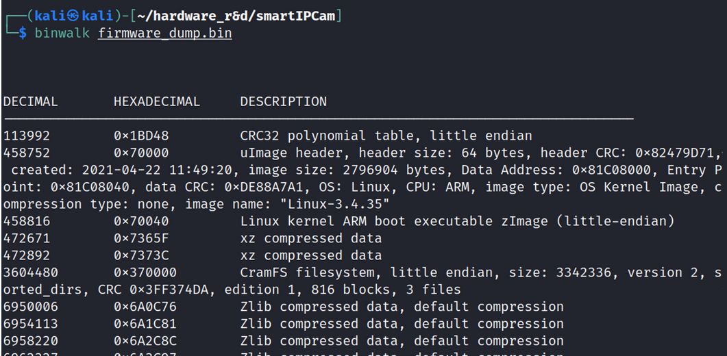
Searching for the strings that I saw in the debug output with strings -td firmware_dump.bin | grep "<string>" indicated that they were earlier in the firmware.
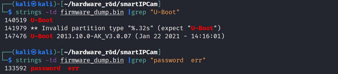
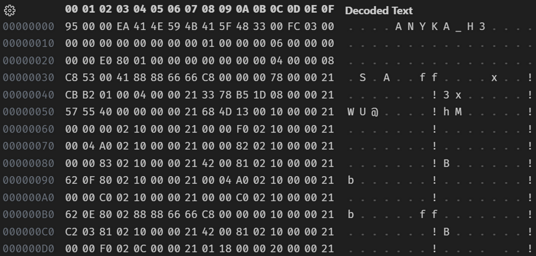
The position that these strings were located indicates that there was a U-Boot image somewhere from 0x0 to 0x70000. Unfortunately, binwalk does not recognise the image. I carved that section out from the firmware image by running dd if=firmware_dump.bin of=uboot.bin count=$((458752-0)) bs=1 and opened in VSCode's hex editor to examine the U-Boot file manually.
I found that it was a custom version of U-Boot with a different header. Where I expected 27 05 19 56, instead there was 95 00 00 EA.
Further down the file I saw a repeating pattern.
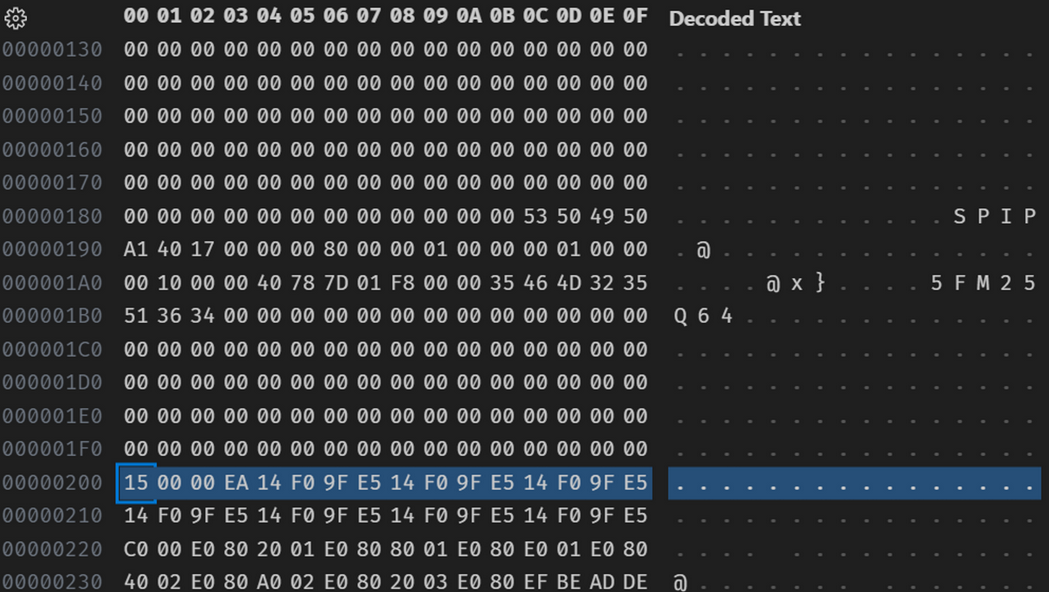
This is a clear indication of little Endian code as there is a high frequency of E0 to EF instructions, which is expected for a ARM v5t microcontroller as indicated in the datasheet. These sequence of bytes also corresponds to known IVT tables for ARM. Nice!
The next step is to decompile the code. My tool of choice is Ghidra. While Ghidra is great, it does still need a little boost when analysing the file. When I threw in the file, taking into account the 0x200 offset, there were still large portions of code that were not decompiled.
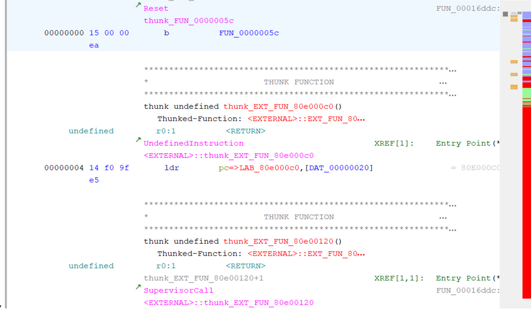
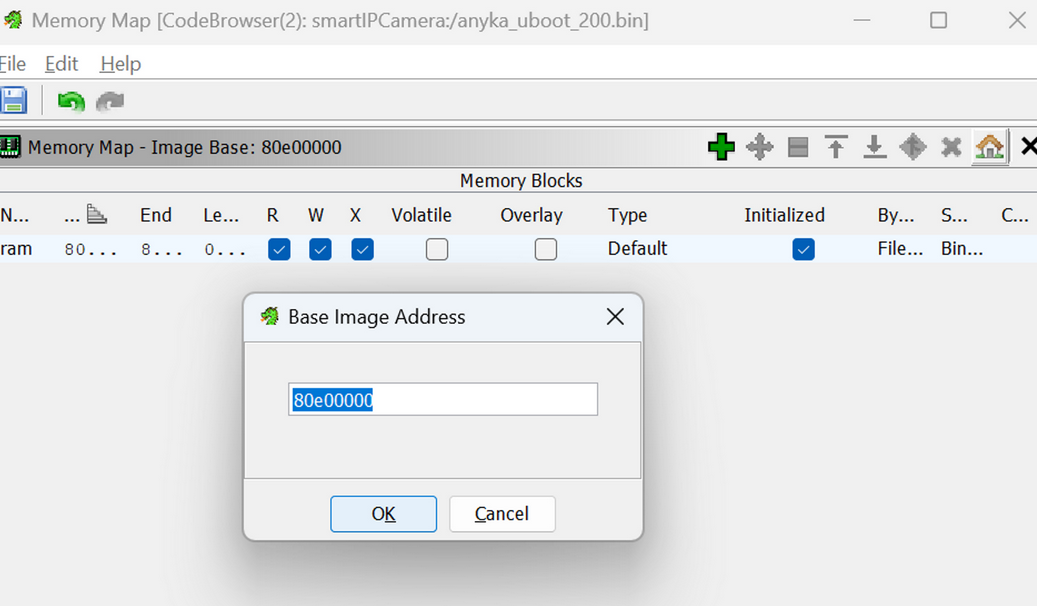
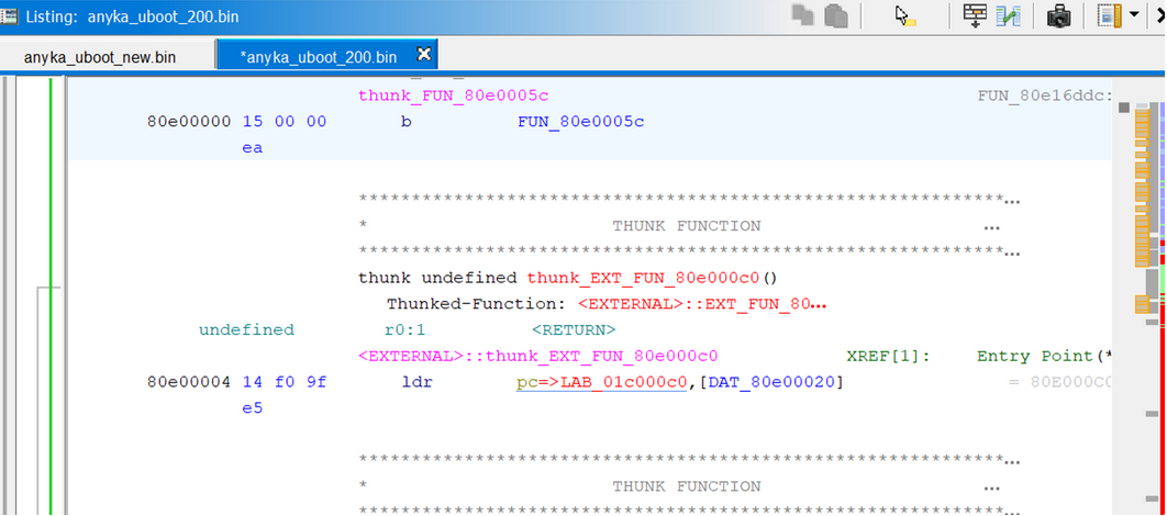
This indicated that the load point was incorrect. A hint came from the 0x4 address where it was attempting to point to 80e0_00c0. A guess is that the load point was 0x80e0_0000. Adding that into Ghidra and modifying the image base address, there were a lot more functions were decompiled after rerunning the analysis.
Locating the string "password err", I found it in the code being referenced by a function.
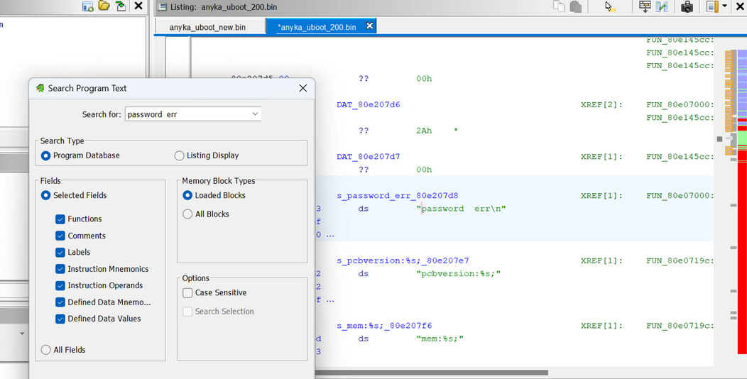
This string is used in the following pseudo-C function. If result of the input string and the password is non-zero, it will reset the device, which is the behavior that we see when we key in the wrong password.
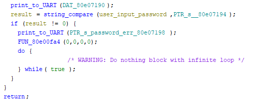
In order to bypass this requirement and obtain access to the U-Boot terminal, we can invert the instruction at this location from beq to bne. Effectively this means any password other than the correct one will allow us to proceed to the U-Boot environment. The instruction to patch is at 0x80e7148.

After patching the instruction and reflashing the device, I obtained access to the console environment of the U-Boot bootloader!
By having access to this console, it would allow me to explore the dynamic environment of the device, as opposed to pure static analysis of the binary.
Notes
- The hex editor for VSCode mangles the file when saving it under a different name after editing a hex value.
- Saving a patched file from Ghidra is also unreliable as it mangles the binary content