2 Revolute Joint Robotic Arm
A final year capstone project. A two revolute joint robot with high torque, speed, and precision. Achieved in hardware, software and electrical design.


What is it?
This is a two-axis robotic arm that was explicitly designed to assist in learning and developing algorithms for robotics. This was a two quarter capstone design course that involved Mechanical, Electrical, and Software engineering.
Why is this cool?
This arm is cool because it is the first low friction, desktop-sized robotic arm that is direct drive. There were quite a number of engineering challenges that had to be overcome to achieve this, and I'm quite proud to be part of the team that designed this robot.
This is quite a lengthy post because I will go through selected design aspect of the robot from conception to implementation. This is broken down into the Design Phase, Prototyping Phase, and the Final Design Phase. I also included some design lessons that I took away from the project.
Introduction

This arm had a number of special requirements. For its educational objectives to be met, the dynamics of the arm should be easy to model. To achieve this, there were a number of requirements:
- Direct Drive. A direct drive is important because it simplifies the dynamics of the robot such as back EMF, backlash, and power to torque calculations.
- Low Friction. Low friction allows the system to be modeled more accurately as it can be difficult to characterize. It also simplifies the control of the system.
- Lightweight. A lightweight arm allows higher speeds to be achieved.
- High torque. An arm is not really useful if it cannot lift itself against gravity.
- Removable Parts. The motor should be designed in such a manner that it can be replaced with another motor or even removed for an under-actuated robot. This allows the system to model different kinds of robots.
- Table Mount. The housing should also be designed so that it can either spin the arm horizontally or vertically. It should be small enough to fit securely on a desk. The design should also be robust enough to stand up to repeated use in a classroom setting.
- Easy control law implementation. The control law for the robot should be easy to implement and require little to no specific microcontroller coding knowledge required.
Some of these requirements directly conflicted with each other. A direct drive motor does not transmit a lot of torque. A lot of motors are designed to spin fast, and torque is generated by adding a gear train. To get a large amount of torque from a motor directly, the coils must be dense and the magnets strong, this all adds to the cost of the motor.
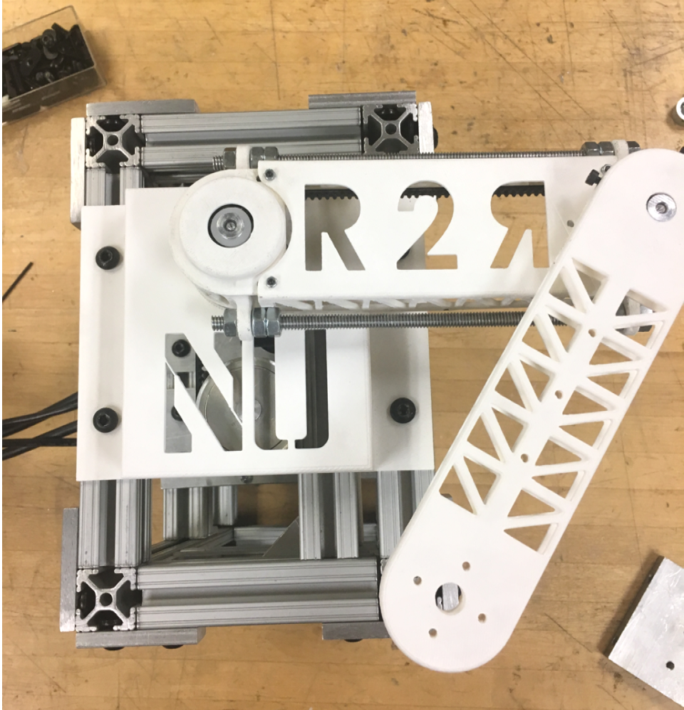
Other requirements limited the scope of the design. Because it was direct drive, the motors cannot be mounted in the joints of the robot, as this would reduce the amount of torque available to accelerate the arm. This would also increase the inertia of the arm and complicate the dynamics. Therefore, it was decided very early on that the motors would be mounted at the base, which created a whole new engineering challenge of driving two independent axes through a single joint.
We spent almost 1/3 of the time of the projects defining requirements because some were not tenable or had to be sacrificed for other, more important objectives. This meant multiple rounds of meetings with the project sponsor.
Design Phase
MCU choice
Because this was a class project, our choice of microcontrollers was constrained to the 32 bit ARM TIVA series from TI, namely the TM4C123 or the TM4C129 microcontroller. We eventually decided to go with the TM4C129 because it had a higher clock speed and we felt that the performance was necessary for us to obtain good control over the robot.
This choice was also partially informed by a department strategy to test the TIVA series as a potential candidate for use in later projects. This also helped to simplify things for the technical lead in the class, as he only had to get familiar with one type of microcontroller and could help us debug issues to a low level.
Another choice was that TI provides quality documentation and their IDE worked pretty well. TI was also pretty responsive to questions that we posted, and the forums usually had useful hints about how to overcome certain issues with the microcontroller.
Encoder choice
We went with Renishaw Orbis magnetic encoders, some of the best absolute encoders on the market, because precision was important for our design. We also chose an absolute encoder because we felt that if it was necessary, it was easy to convert it to a relative encoder in code. However, the opposite might not be true.
Another reason why we went with Renishaw was that one of our team members had experience working with the encoders, and in paraphrase and more polite terms, "were a dream to use."
Motor choices
We decided on using NEMA 23-style BLDC motors from a lesser known company, Koko Motion. Our early decisions were based on the cost of the motors, as their torque equivalents from better known companies were 2 times the cost or were unavailable. It was also hard to get hold of someone who would sell us the motors as we had to call companies to get quotes for the motors we saw online. In fact, our torque requirements were so similar to another team in the class that we both identified the same motor: EC90 flat from Maxon motors. The problem was that there were only 3 motors in stock and the lead time was 6 months! We eventually decided to source for other motors and the other team 'bought up the entire North American stock', which is kind of fun to say.
It was also hard to source direct drive motors that had the torque we wanted because most motors came geared.
However, you get what you pay for, and the datasheet that came with the motor was quite useless and we had to figure out the hard way to get the motor to spin.
Mechanical choices
We decided to design with Solidworks because most team members had the most experience in that software. For stress analysis, we relied on Ansys.
We oscillated between using metric and imperial, and despite the declarations of 'metric, definitely metric', we settled on imperial because it was impossible to manufacture parts accurately using metric in a shop outfitted with imperial equipment.
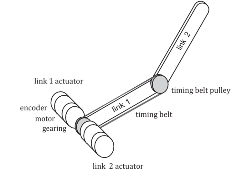
The design of the shaft at the bottom of the arm was also the most complicated.
This was because we had to independently control two axes of rotation through a single axis as well as consider the joints and the housing of the arm and the motor box.
Prototyping phase
The software started first because we didn't have the motors or the arm yet. Since we weren't sure how everything was going to be connected, electrical also had to wait for mechanical to complete their designs. (At this point we started to refer to our sub-teams as electrical, mechanical, and software. You would look at someone and go, "How's software coming along?" or "What's software doing this week?". It was a little strange for electrical as it was a one man team. "Electrical didn't get any sleep last night.")
So what little work there was to do, we tried to get it done because we were quite aware of the potential issues that we could face. Software started by getting familiar with the IDE and using the communication modules like SPI and I$^2$C, while mechanical designed the arm. Electrical started on the datasheets and the general layout.
Since we knew what encoders we wanted (the very best ones), we had mechanical build up a test jig, which we hooked up the microcontroller. Because the documentation was relatively well written, it took us about a day to get working. One issue that we faced when installing the encoder was that it had to be a certain distance away from the sensor. We always adjusted it by hand, but much later I found out that another team had 3D printed jigs so that they would always install the encoders correctly.
Motor troubles
We had a few issues with the motors. Because the documentation was so poor, it took us awhile to connect the right wires to the right terminals. TI provided a GUI that would connect to an MSP430 breakout board that would connect to the motor controller breakout board and spin our motor, but we weren't able to get it to work at the first try. Upon closer examination and some suggestions from the technical lead in the class, we realized that we needed pull-up resistors on the Hall sensor outputs in order for the motor to work after examining the output of the sensors on a scope while turning the shaft manually.
We then examined the code for the GUI in an attempt to replicate the commands for our chip. However, because it was designed as a GUI, there were other elements mixed into the code that made it difficult to separate SPI commands to the motor from all the other modules that were talking to each other. Furthermore, the architecture was different, and it relied on direct register manipulation, making it difficult to port code over to the TM4C, which we were already using the Tivaware library for.
We eventually decided to write our own library, and that took almost a week because the motor controller chip was not talking back to us, despite having checked and rechecked and modified the SPI code to use different modes, different bit rates...etc. We even examined the chip to determine if we were using a different version (there was a hardware and a SPI version). We finally determined that SPI was not functional even though power was supplied to the chip if the Enable pin was not pulled high.
Development Phase
The development phase tracks the development of specific key items in the robot's design.
Mechanical
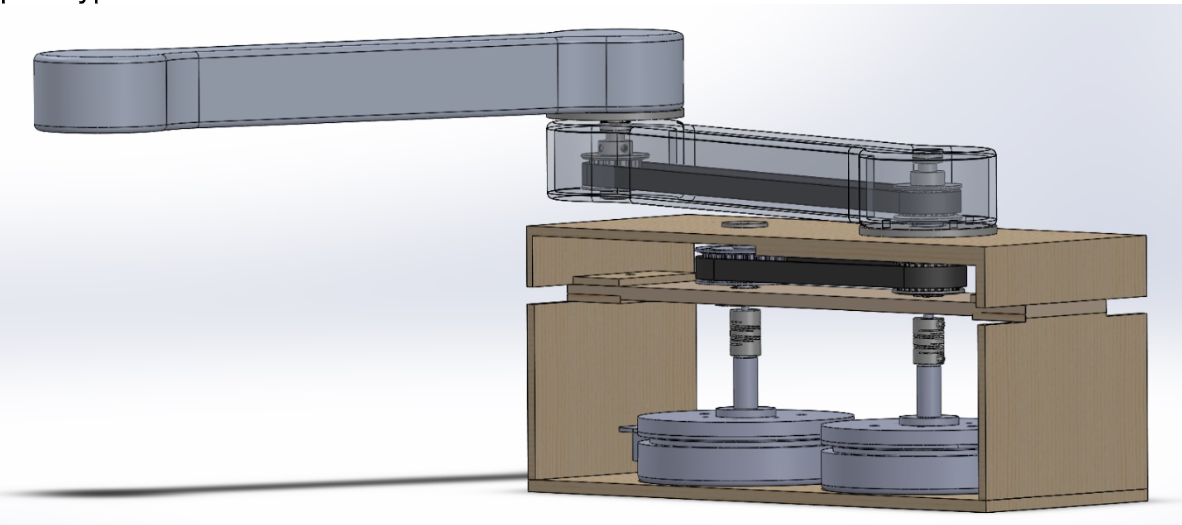
This particular model relied on 'pancake' motors as models from Maxim. At this point the arms were not optimized and the housing was just to visualize how the system fit together.
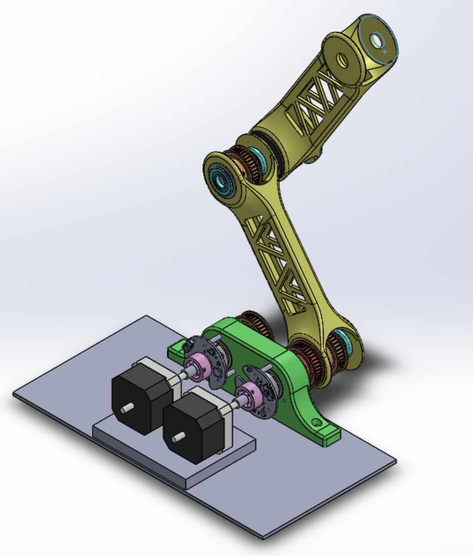
For this prototype, the housing had yet to be done, but the design of the first shaft was complete and the microcontroller code for the motors was finished, so we could demonstrate position control. The links were also optimized to save weight. However, one big issue was that assembly was difficult because we didn't have any means to tighten the belt, so the belt had to be stretched out and fitted to the gears: not ideal when you don't have a ton of space to work with, and the gears have to be fitted onto shafts. This took a long time to assemble, and there was always a trade-off between ease of assembly and tension.
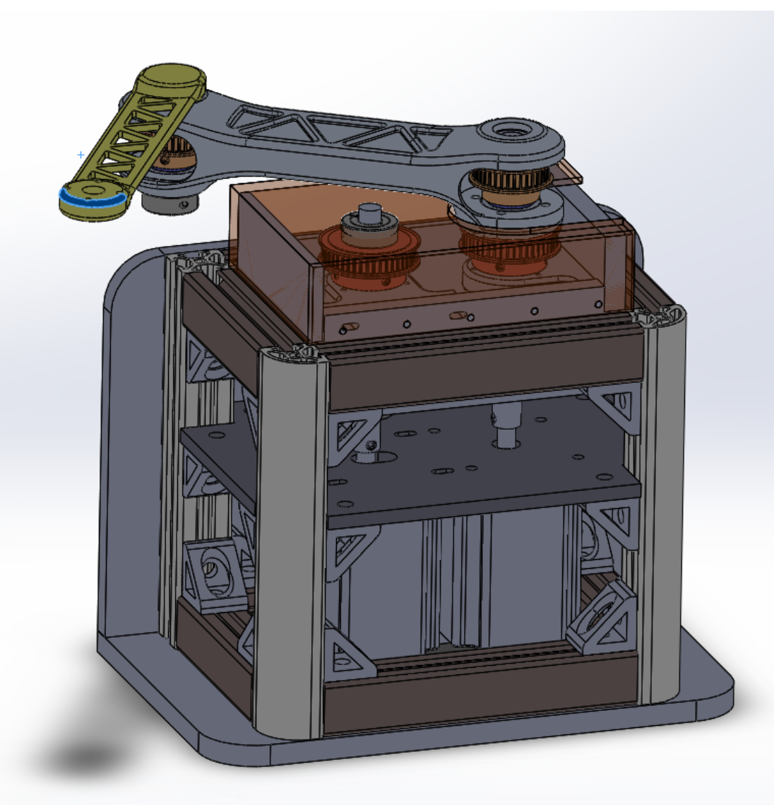
The housing was designed to use 80/20 aluminum and the second link was made smaller. However, the assembly was fiddly and difficult, and took a considerable amount of time to align everything.
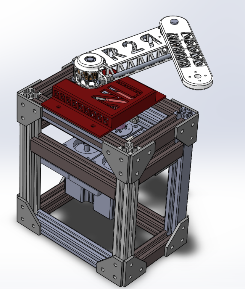
The final design had some radical changes to the links. Instead of printing the entire link, only the ends were printed and instead were held in place by aluminium rods. This made assembly faster and tensioning was a breeze. The middle portion was just a cover to protect the belt. The width of the last joint was also expanded to reduce the flexing. The design of the housing is also more open, which again, simplified the assembly.
Final Design
This portion will focus on selected aspects of the final design.
Mechanical
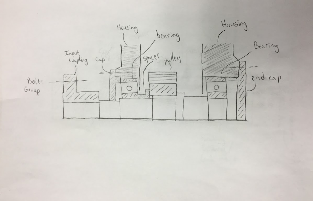
Shafts
A significant amount of analysis went into optimizing the shafts. A lifecycle analysis was determined for each shaft to minimize the dimensions for weight savings.
Link Analysis
Each link was accurately modeled in Solidworks and the forces were applied to each structure.
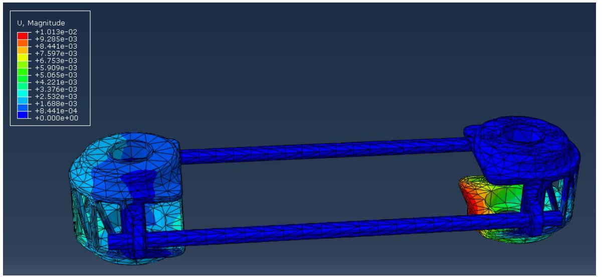
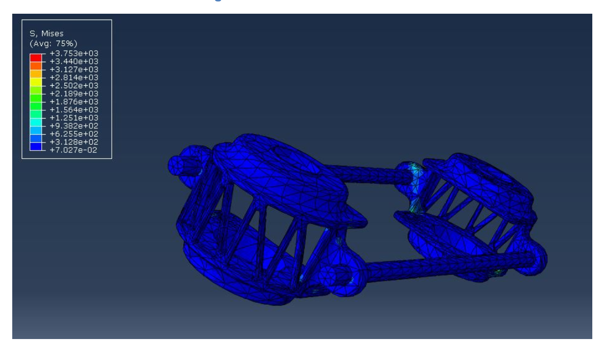
Most of the shape was for alignment, and weight was actively minimized. The maximum deflection was 0.01" with a factor of safety of 50.
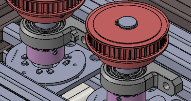
Adjustable Bearings and Motors
The motors and the bearings were mounted on sliding pillow blocks to allow proper tensioning of the first belt. The encoders were also mounted here instead of the motor shaft so that they can be reused each time.
Adjustable Housing
The housing was made of 80/20 aluminium which not only provided the necessary rigidity, but also the weight to hold the robot down as the arm can create a significant amount of torque when it is spinning at full speed. We actually had the acrylic base plate of an earlier prototype crack because of this.
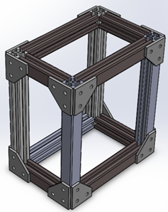
The links are also easily available on McMaster Carr.
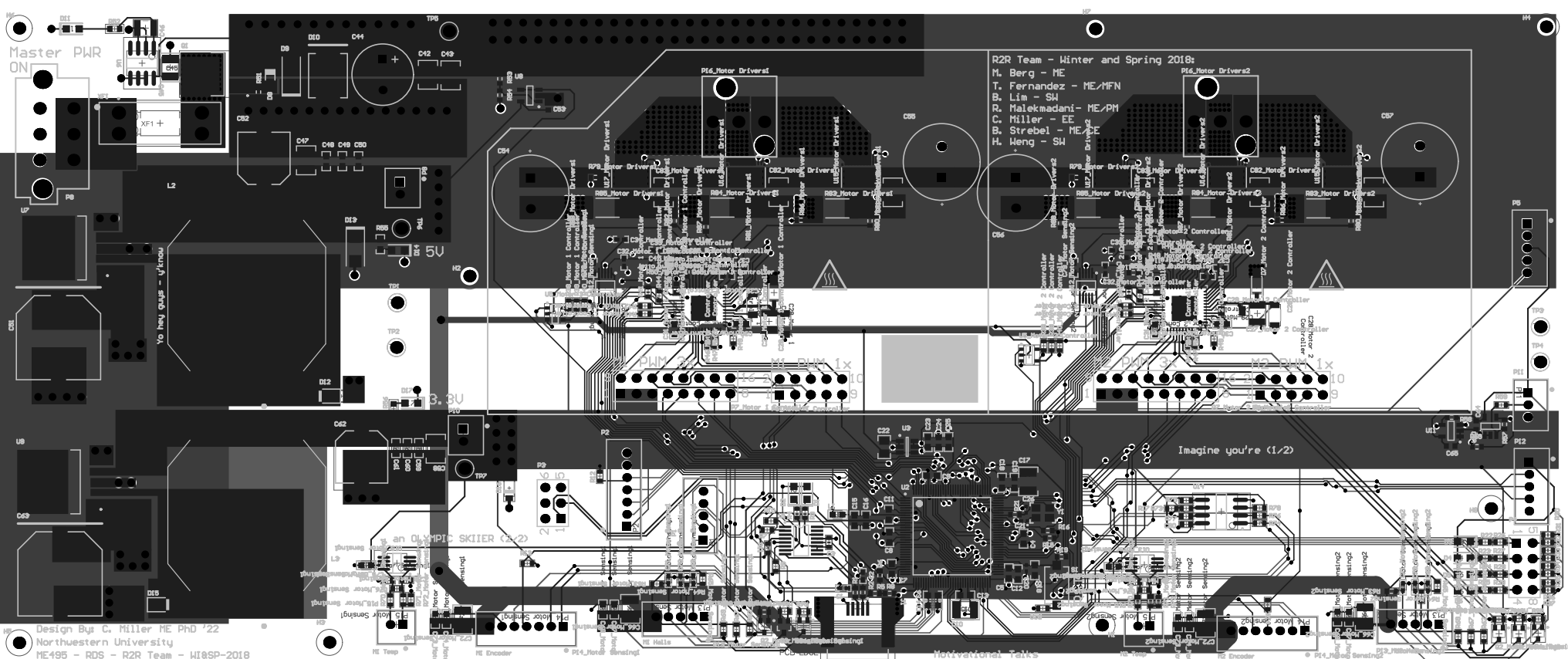
Electrical
Wide voltage and current range
It was intended that the motors might be swapped out, so a wide voltage range was designed from 22VDC to 56VDC. The peak current draw was 11A per motor. In order to protect this, reverse polarity protection was also designed into the circuit using Zener circuits. Over voltage protection was also designed with a Zener diode circuit, with the microcontroller monitoring the voltage of the primary input rail to account for the motor's regenerative effects.
TI TM4C129
We chose this microcontroller because it had the higher clock speed of the two that we were given, and it had sufficient SPI buses to communicate with the encoders and motor controllers on each bus. This allowed for faster communications. It also had more GPIO pins, which was required for all the sensor and circuit monitoring that we were doing. We used 70 out of the 90 GPIO pins.
TI DRV8323RS Three-Phase Smart Gate Driver
Motor driver with a large voltage range and designed to run BLDC motors with in-built commutation tables and current sensing capabilities.
Reinshaw Orbis Absolute Encoder
This encoder had 14 bits and utilized a magnetic encoder. This prevents improper readings due to light, dirt and other environmental conditions affecting optical encoders. Because it is also non-contact, it also reduces wear-and-tear effects on the device.
An important point was that it was absolute, and it allows repeatability and homing features.
Software
Motor Decogging
We implemented decogging in order to reduce the torque ripple. This is important to ensure the best performance of a motor. Because a BLDC motor has a discrete number of coils, cogging is experienced. This is where the magnets on the rotor are aligned with the coils on the stator. Here, the interaction is the strongest, and consequently the torque experienced is the strongest. Therefore, as a BLDC motor turns, there will be a small variation in the torque experienced based on the position of the motor, and consequently this will result in errors in the control model because it assumes a constant torque.
To reduce torque ripple, a precalibrated feed-forward current, dependent on the absolute position of the motor shaft, is applied to the control law. The calibration is done by commanding the motor to hold a position while the system measures the desired position, the recorded position, and the current flowing to the motor.
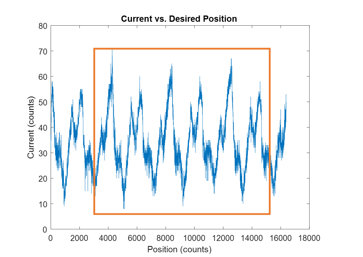
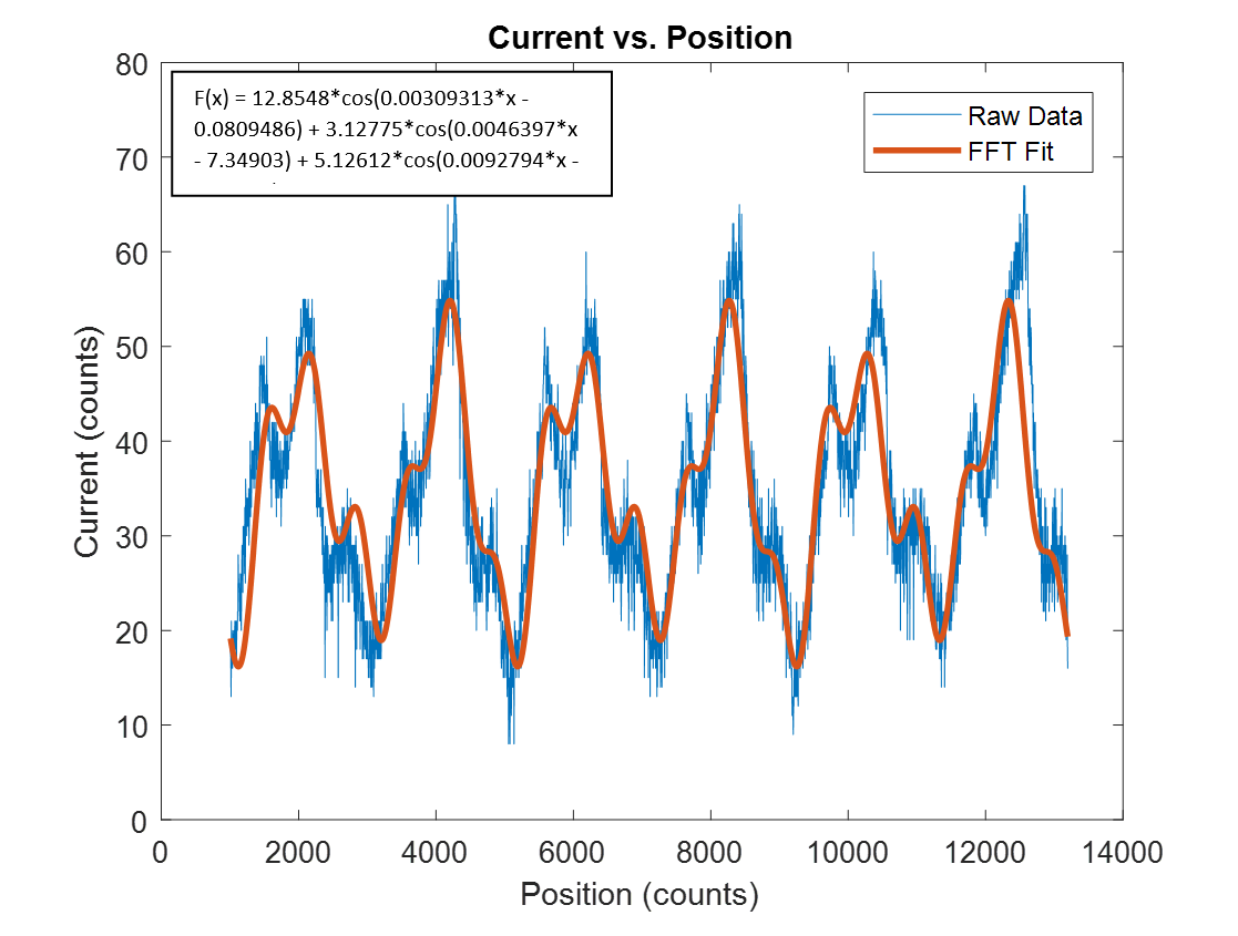
Here, the ripple is seen based on different absolute positions. This is characteristic to each motor. If there was no torque ripple, we would see a flat line with the current value determined by the motor constant. An Fast Fourier Transform fit is then applied to this data to determine a best fit, and then the equation is applied directly as a feedforward term for the control law in the microcontroller.
We then determined that motor decogging was correctly implemented by measuring the position error with and without decogging.
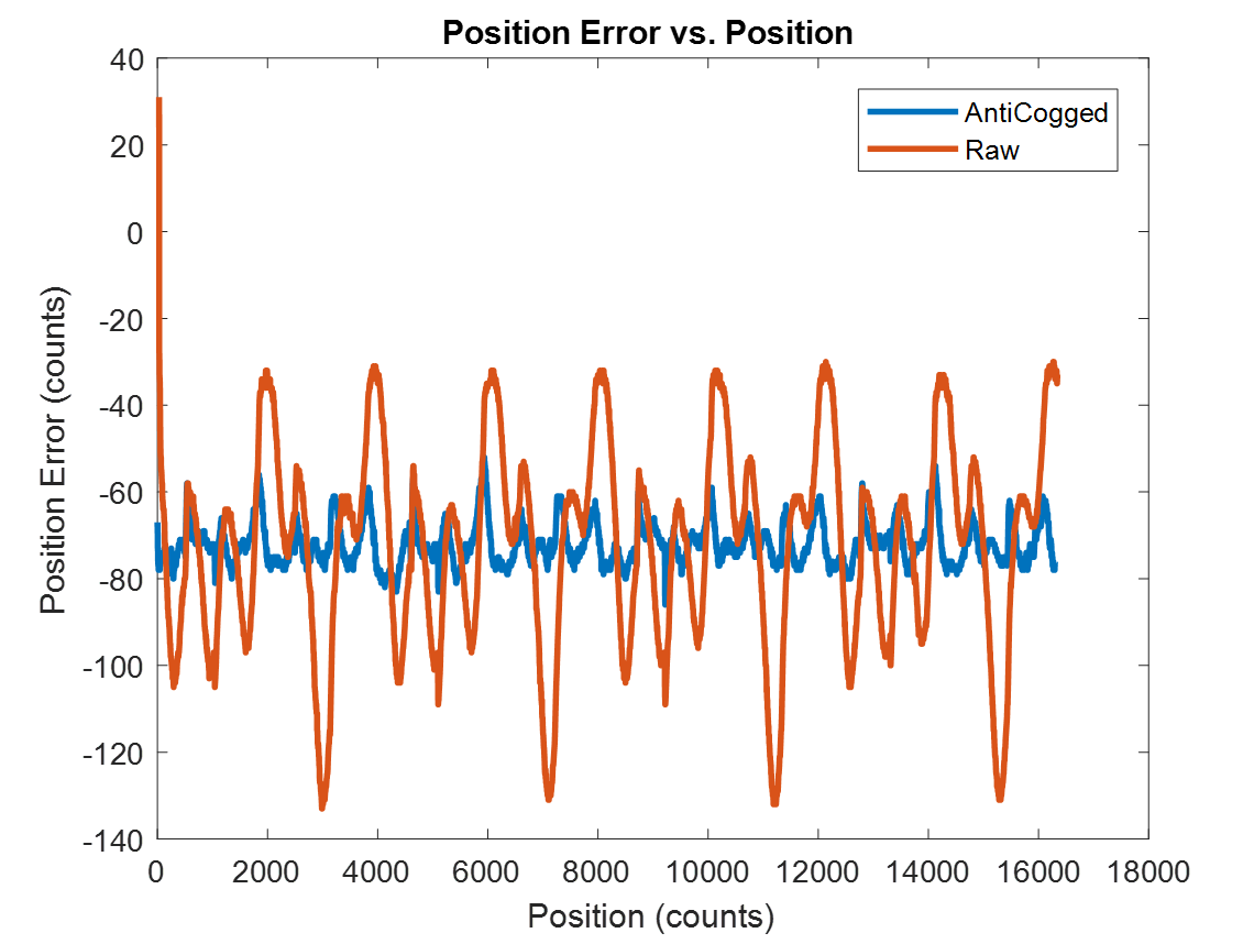
The position errors are significantly smaller for the same controller, and in this case motor decogging was successfully implemented.
MATLAB client
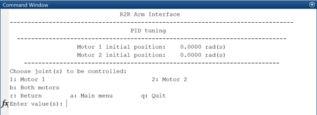
We wrote a MATLAB client that would talk to the microcontroller through a serial interface. We chose MATLAB as this robot would be used in an educational setting and most of our users would have MATLAB installed. We were also familiar with the interface and would not need to develop a GUI for our application.
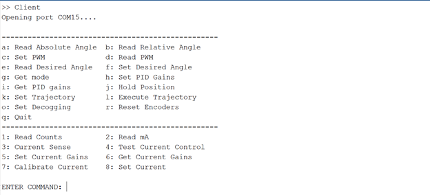
The client would update the command prompt in MATLAB based on the context of the current selection. While we had spent a significant amount of time developing a linked menu option, it became complicated to implement and we decided to develop a simpler interface due to time constraints.
Documentation
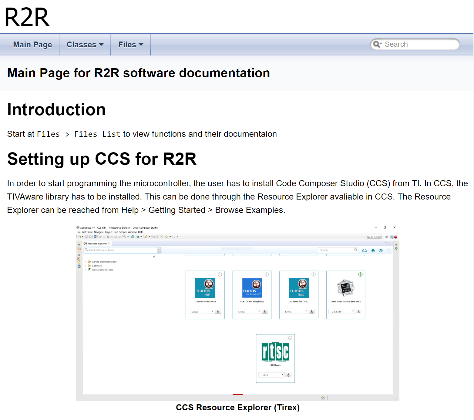
Almost every line of the code was documented in doxygen with examples provided for major functions. The project page is hosted on Github and it not only provides documentation for the code, but also instructions to set up Code Composer Studio and common pitfalls.
Complete documentation allows the project to be improved easily by future teams.
Problems
Mechanical
Assembly of the housing was difficult because the arm had to be able to rotate vertically and horizontally. The design of the assembly required very precise fits, or multiple moving parts that had to be done by hand within a constrained area, therefore assembly usually took an hour, and fixing anything was difficult once the robot was assembled.
Electrical
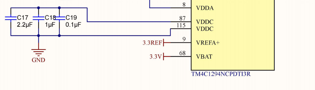
None of us caught this before it went into production, despite multiple design reviews and to be fair it is a really subtle error until you look really closely. VDDC is the output from the internal 1.8V regulator of the TM4C, and caps must be attached to the pin in order for it to work correctly.
The chip burnt out immediately because the regulator was tied to ground on pin 115.
Solution
The leg of the pin 115 was bent off the pad and wire was soldered from it to pin 87.
Sparking
We experienced sparking on two boards. One board completely burnt the entire 3.3V line while the other broke the microcontroller. Factors that contributed to this were untidy electrical workbenches with stray bits of wire and variations in component lifetimes.
We had a professional engineer look over the design of the board and he could find nothing wrong. We spent a considerable amount of time reevaluating the design, but we couldn't find any problem with it. Our second board failed a few days before the final presentation. We performed all possible repairs until informed by the project sponsors to cease repairs on the PCB and we had to revert to our breadboarded design.
Solution
We trashed the first board and replaced the microcontroller on the second board. We reverted to the breadboarded design when the second board failed before the final presentation
Crystal did not work
The pads for the crystal were reversed, and we were having trouble using it as the code would always be stuck on initializing the external clock. We tried reorienting the crystal, but that didn't work.
Solution
We used the internal crystal, and it was accurate enough for us to use UART to communicate with our MATLAB program.
Software
Hierarchical menu
We developed a hierarchical menu to guide the user in making selections at each step. This is because some menu options involve several sequential steps by the user. However, the implementation became complicated on the back-end, and we weren't able to develop it quickly enough for actual debugging.
Solution
We stopped the project and reverted to our state-based simple menu for debugging and improved the user experience based on what we learnt from the hierarchical menu.
GUI
It was desirable to have a simple GUI in order to test the robot's functioning status instead of relying on the command line. However, the code developed for the robot kept changing and the development of the GUI was not fast enough to catch up because time was spent on developing a simulation of the robot in the GUI and live-plotting function.
Solution
We stopped development on the GUI and implemented the live-plotting in the simple menu.
Lessons learned
Extra features last/Debugging tools first
A lot of time was spent developing user-based tools in software that eventually were scrapped. This is a classic case of focusing on making it pretty instead of functional. While we thought we had a functional product early on, it was discovered that we needed a debugging interface, and trying to implement that on a 'prettified' interface was difficult and time consuming.
More focus should have been spent getting the basics working rather than the interface design because: an interface is not the main deliverable, and we are not interface designers. It is comparatively less efficient for us to design a good interface than it is to write a comprehensive debugging interface. A future team would also benefit more from a simplified interface for debugging than a pretty but complicated interface.
Software that everyone uses
The software might not be the best, however there is a benefit because other people can edit and look at your designs. It made sense for Electrical to use Altium for our project because:
- Electrical was a 1 man team
- Electrical had motivation to learn Altium
- Electrical had at least 2 years of industry experience in designing power electronics with Altium
Electrical was really competent at what he did. For the most part I think we were secretly happy that 1/3 of the project was being handled well.
However, when there were issues with the board, none of us could help diagnose it, because we didn't have the software and didn't know how to use it, so that put a lot of stress on Electrical to get it right.
Later on, after the project had ended and I was looking into the design, I realized that I would have to replicate the entire design in Eagle if I wanted to modify it, so that hampers future design and iteration. Using an unique software is not necessarily bad, but I think it is something important to talk about in a project that might extend over multiple teams.
Sometimes you should use a breakout
The two times our board failed, there were reports of a spark. Eventually it was determined to two high voltage vias near the motor controller that caused the visible and audible arcing.
Designing the motor controller into our board took up a considerable amount of space and cost because of all the power electronics components and electrical isolation requirements.
Looking back, if we had designed the motor controller to be plugged in as a breakout board that TI had already designed, we would have a part of the design that we knew worked, and could replace if there was an issue.
Design for Assembly
Consideration should also be placed for assembly and repairs. Sessions would be scheduled just so there would be sufficient pairs of hands to assemble the robot. This was very time consuming especially if a part had to be replaced for fixed, as it is often with prototype designs.