New Flight Altimeter for Model Rocketry
A modern flight altimeter with BLE!

TLDR: This post documents my lessons on building a flight altimeter for model rocketry. It is built with solving a few pain points in mind: 1. Output basic diagnostic data when it is installed in the AV bay. 2. Collect orientation data.
I realized that I would always use the same components for my flight computers/altimeters: 9 DOF sensor, altimeter, SD card storage. Having all of these already on a single board would prove immensely helpful.
I also included a bluetooth module so I could easily obtain information about the board and setup in real-time on the launch pad because it is very annoying to set an entire rocket up for launch and go to the launch pad to find out that something is wrong with the AV Bay.
My early designs used a Teensy 3.6 because it was fast and had a microSD card slot, so there was no need to design for an additional component. I combined it with a GPS, a BMP180 for altitude sensing, and a BNO055 for orientation. Some additional components was a high current DC motor controller, XBee for telemetry, but those were only necessary for the competition at the time. This board had a few problems, and it was unable to collect the data due to corruption of the SD card. We were never able to read the SD card after launch. I also never used the GPS because it is possible to track the rocket visually 95% of the time.
I set out to build a new flight altimeter that only included the bare essentials.
Stage 1: Data collection only
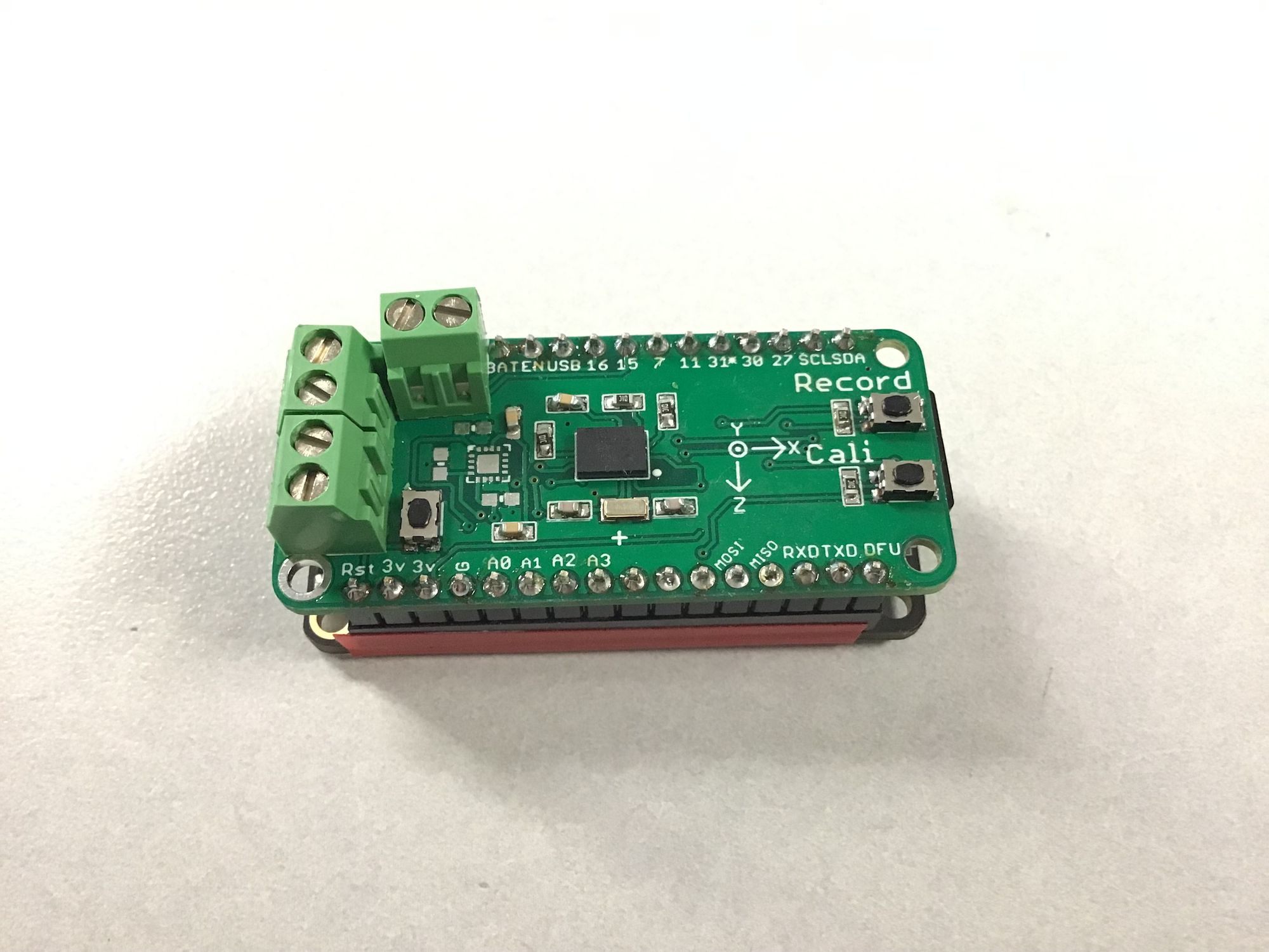
This version only features data collection. It includes a BNO055 for orientation, an ADXL377 for high G measurements, and a MPL3115A2 for altitude sensing. It has a microSD card slot on one end for data storage, and uses a FeatherWing layout for compatibility with Adafruit's Feather board series. In my case I am using the nRF52 Feather board so that I can communicate with the board over Bluetooth. It has a pad for a MOSFET, but that is only for testing.
This board lacks beepers for audio, and buttons for tactile feedback. These are not critical components and will be included in the next iteration.
I found some critical problems with this version. Because the pins are not tied high or low, they would start recording randomly. A fix was implemented so that the recording can only be activated over BLE. The connections to the MOSFET was flipped, so it didn't work when more than 0.6V was applied.
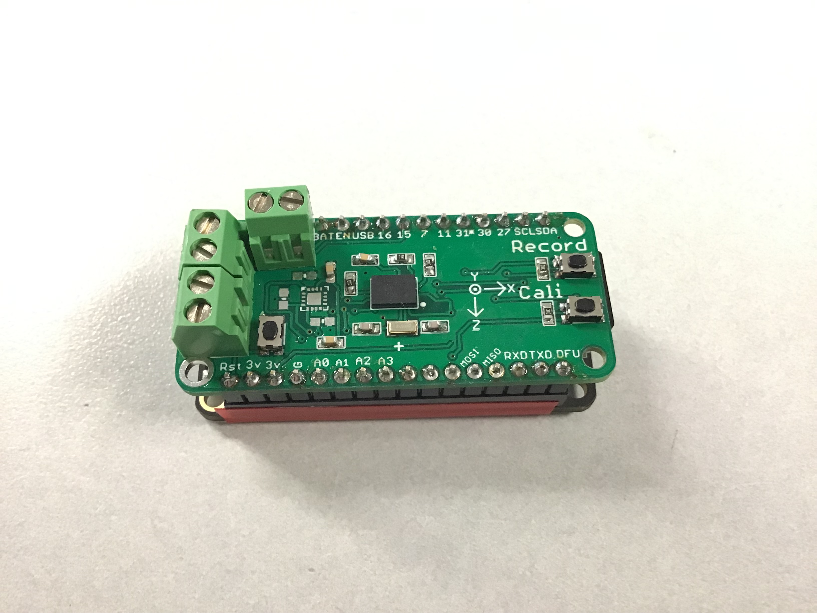
Stage 2: Connectors and Orientation
The MOSFET was fixed with this iteration, and larger connectors were added. Note that I left off the 200g ADXL377 sensor on this version because it was not available at the time.
Tilt angle calculation
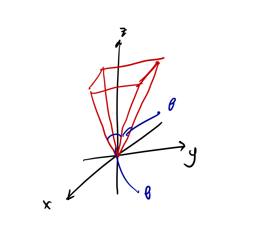
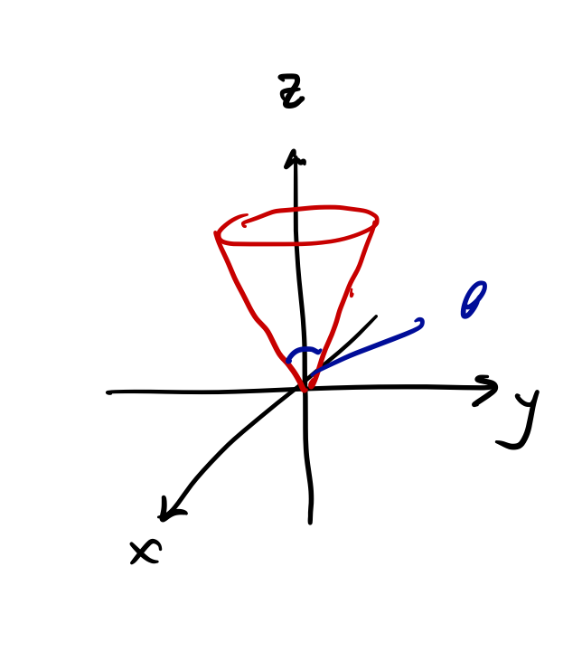
Previously I used Euler angles to limit the rotation, however I ran into some issues. One was that if I used a simple limit in the x and y orientations, then the tilt of the rocket would not be constrained to a cone, but a four sided pyramid.
Instead, I used quaterions, which are also provided by the BNO055 sensor, to determine the orientation and the tilt of the board. A quaterion describes a rotation around a unique axis to get an object from one orientation to another. It has 4 values, one real, and three imaginary. The three imaginary values are the x, y, z of the rotation vector, and the real value describes the amount of rotation required. It acts like a normal vector, and normal vector operations can be applied to it.
When I turn on the BNO055, it gives me a quaterion. This quaterion, $a$ describes a rotation from the 0 position (wherever that is) to this new position, which we will call $A$. Now when I rotate the BNO055, that gives me another quaterion, $b$ from 0 to another position which we will call $B$.
Now we want the quarterion, $c$ that describes the rotation from $A$ to $B$ position, ie $b-a$. Since all our quarterions are unit quarterions, this is easy:
\[c = conj(b) \times a \]
Lets say that the initial orientation of the rocket was in the positive z direction. Note that $c$ is not the rotation of the rocket from z axis to the new position. It is the axis of rotation. If we want to find the new vector of the rocket, we simply take the original vector of the rocket and rotate it by $c$. So we take the z axis quaterion and rotate it by $c$, and this gives us the new vector of the rocket. Now the tilt angle can be calculated by taking the dot product of this new vector with the z axis.
Software
In this version additional options such as turning on and off the energetics, modifying the tilt angle, and even the default orientation of the sensor is included in the available BLE commands, allowing the board to be mounted and then being configured from the outside. I think this is very useful as it allows the board to be tested without being tethered. I tested the altitude sensor by placing the board with a battery into a vacuum chamber and viewed the live data of the expected altitude at a given pressure.
Launch Day
The board was launched on a L3 certification rocket at Richard Bong State Recreation Area on June 10 2019. It was mounted on a custom sled and powered by a Li-Po battery. The battery was fully charged the day before, but because the avionics had to be mounted early on, the heat caused the battery to report 30% battery power on the launch site. When the rocket landed, the system was not recording.
The system was recording and locked before launch, so any button presses would not have registered. The system was still powered when we approached the landing site, so there was battery left. That leaves only two possibilities:
- During launch, the G-forces caused the reset button to be depressed, causing a reset.
- The G-forces in flight might have caused the battery to drop below the brown-out limit and caused the system to reset.
Of these I believe the second is the more likely. The buttons were oriented perpendicular of flight axis, so the G-forces would not be likely to be acting in the same direction to depress the reset button. The switch is rated to 300gf, or 3N, so if the switch itself is 5g, it would take 60G to depress it from the acceleration.
Potential Solutions
- Remove all reset buttons prior to flight
- Replace Li-Po battery with a 9V soldered battery.
Additional Notes
There were several launches from the NUSTARS team that day, and we collected some useful insights:
- Having a tracker and being able to use it allows you to find your rocket 10x faster than romping through a muddy field.
- Posting someone down the range really helps in narrowing down the search area
- LoRa works really well. One of our rockets did not deploy when it was launched, so it came down ballistic. But the system remained transmitting throughout the entire flight with a simple wire antenna. Previously when we used XBees we only received about 300ft of range. This was well over 8000ft, an amazing test of the LoRa.