Lightbeans Part 1, Programming and Circuits

Lightbeans is a series of new tutorials for the ULCEK kit that is aimed at new users. It is a project to make a self-activating night light with the components in the ULCEK kit.
Let's start!
First we will learn the basics of Arduino and how to program it.
A number of programs are required:
- The Arduino IDE (required for programming)
- Board definition installation for the WeMos ESP8266
- Driver installation for CH340G (Windows) or CH340G (Mac)
Note that you should install the Arduino IDE instead of the Arduino Web Editor.
A set of CH340G drivers for the ESP8266 are also available on the manufacturer's website. The usual caveats of downloading files from the Internet apply.
Programming
Following the time-honored tradition of all guides, a blinking LED will be your "Hello World!" for electronics.
You are using a microcontroller to interact with the LEDs. A microcontroller is essentially a tiny computer that runs one program.
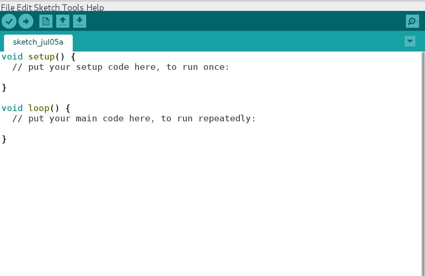
Figure 1. Initial opening of Arduino IDE
When you first start the Arduino program, an empty window will pop up. This is where you'll be writing your program. In the Arduino IDE, this is known as a 'sketch'. Notice that there are two lines, one which is the setup, and the other will be the loop. The curly brackets {} are limits to show what lines does setup or loop contain.
When it boots, the microcontroller will run all the commands in setup once, and then run the commands in the loop in sequential order. When it reaches the last command in loop, it will then jump to the first command in loop until it is powered off. The setup will be where we declare to the microcontroller what pins we are using and the loop will instruct the microcontroller what to do in each cycle.
We'll have to declare to the microcontroller that we are using the onboard LED.
In Arduino, we use pins to send and receive data. These are the little pointy things on the Nano or WeMos that plug into the breadboard. By sending data to these pins, we can control other electronics components.
In the following code below I will be using comments. These are parts which the program does not read and you'll see them to be grey-ed out. They are anything that follows // on that line. If you remove the // the code will be read by the Arduino IDE again. This is useful in adding comments to clarify what your code is doing as well as to test your code.
Enter the following between the braces {} after setup.
pinMode(BUILTIN_LED,OUTPUT);
pinMode is the function that helps us to declare what the pin is going to be. But we have to give it two inputs: the pin number, and what the pin is functioning as. The onboard LED on the board has a reference of 1, so we are going to use 1 to refer to it. Since we are sending a signal to this pin, we are going to use it as an OUTPUT. You will see Arduino highlight OUTPUT in blue because it is a keyword. All blue words serve a specific use and should not be used as variables. You can see all pin definitions in Chip Capabilities.
Some variables are already defined. In some cases we can also use BUILTIN_LED to specify the onboard LED for the ESP8266. This has already been defined for us elsewhere in the code. You can also use the numbers printed next to the pins to determine which pin will be activated.
Reminder: Programming in Arduino is case-sensitive.
Remember to add ; after you complete a command. This acts as a delimiter, much like how spaces in sentences help to form words. Without it the IDE will not be able to understand whatyouaretryingtosay.
Great! Now how shall we blink our LED? One second off, two seconds on? In the loop portion of our program, write the following.
digitalWrite(BUILTIN_LED,LOW);
delay(1000); //delay counts in miliseconds
That settles the off portion of our loop, can you guess the on portion?
digitalWrite(BUILTIN_LED,HIGH);
delay(2000); //delay counts in miliseconds
Never had any doubt in you. delay as you might have guessed, stops the microcontroller. digitalWrite tells a specified pin to go either HIGH or LOW, and this physically means that it turns a pin on or off.
While you are typing your code, you can space out your words to make them more readable.
Note that whitespace in Arduino does not matter.
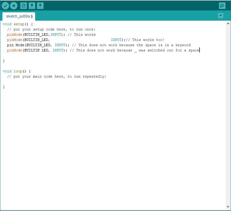
Figure 2. Whitespace examples
Now plug in your chip and click the upload button!
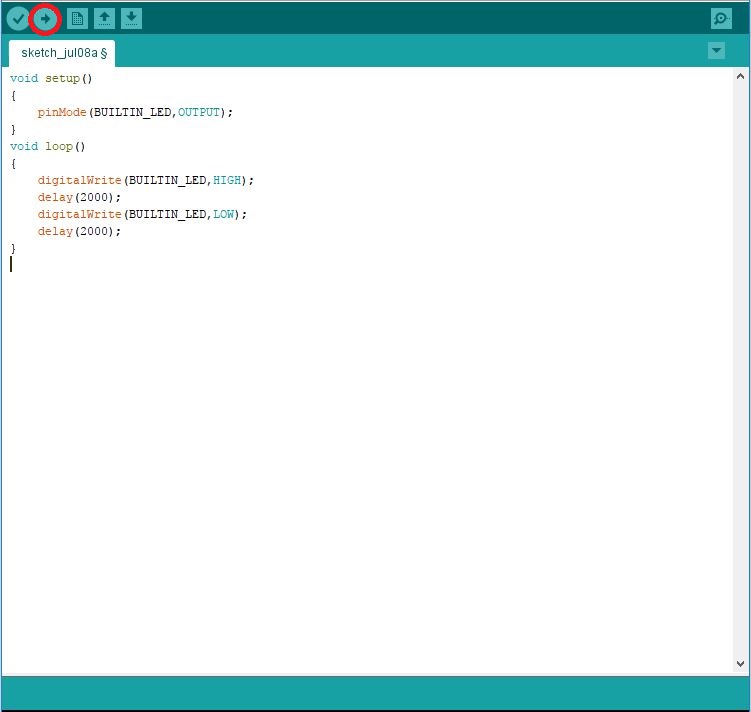
Figure 3. The upload button is highlighted in red
Sketch
//#define BUILTIN_LED D4 //for the ESP8266
#define BUILTIN_LED 13 //for the Nano

void setup()
{
    pinMode(BUILTIN_LED,OUTPUT);
}
void loop()
{
    digitalWrite(BUILTIN_LED,HIGH);
    delay(2000);
    digitalWrite(BUILTIN_LED,LOW);
    delay(2000);
}
FAQ
-
Help! I have a Mac and it doesn't work!
Try using a usb extension or a USB-2 port. The USB ports of the newer Macs are recessed and the data pins might not touch. Trying different USB ports might also work.Check that it isn't a driver issue. If it is, please look up on how to install a CH340G or CP2104 driver for your particular configuration.
-
Help! The compiler is giving me an error!
Did you complete braces{}, use()and all delimiters;? -
Help! How do I upload code?
For the Digispark, upload the code first, then plug it in. For the ESP8266 and Arduino Nano board, plug it in then upload your code.
What you learned
- How to define output pins.
- How to upload a sketch.
- How
digitalWriteworks. - How
delayworks.
Additional Projects
- Can you change the period that the LED blinks?
Circuits
Excellent, now that you are able to blink an LED, the next step is to learn how to wire external circuits. Usually external circuits have two links to your microcontroller. They must be powered, so they will have to use power and ground, which is like + and - on a battery. Sometimes we might also want to control the other pins, so there might also be additional wires to other pins on your microcontroller. Note that the other pins can sometimes serve as + or - in the circuit.
We will blink an LED again, except this time we will move it to to the breadboard. The difference is that we are connecting an external circuit to our microcontroller by giving one of the pins an output signal (much like how everything is run).
This is important because the signal must be the right kind. Some components might be expecting an electrical signal of a specific order, and when this is incorrect, we get data corruption.
Luckily for us, a Light Emitting Diode (LED) is a relatively simple component. It takes an input voltage and converts it to light. However, it can only take up to a certain voltage before it burns out. We don't want to burn out our LED, so how should we wire it?
The simplest way to do so is to put a resistor in series (on the same line) as our LED, there are no splits in the path that the electricity takes. The resistor helps to split up the voltage and prevents us from supplying a voltage that is too high to our LED. For a 5V supply, any resistor from 330 to 1kΩ is suitable. The wires coming out of the LED are known as leads, and the longer lead always goes to the higher voltage.
WARNING: Not connecting a resistor in series with your LED will cause it to burn out or in rare cases, explode. So remember: ALWAYS connect a resistor in series with the LED.
To do this, we will use a breadboard. A breadboard is super useful for prototyping designs and circuits because you can connect components electrically without having to solder them together. A breadboard looks like this:
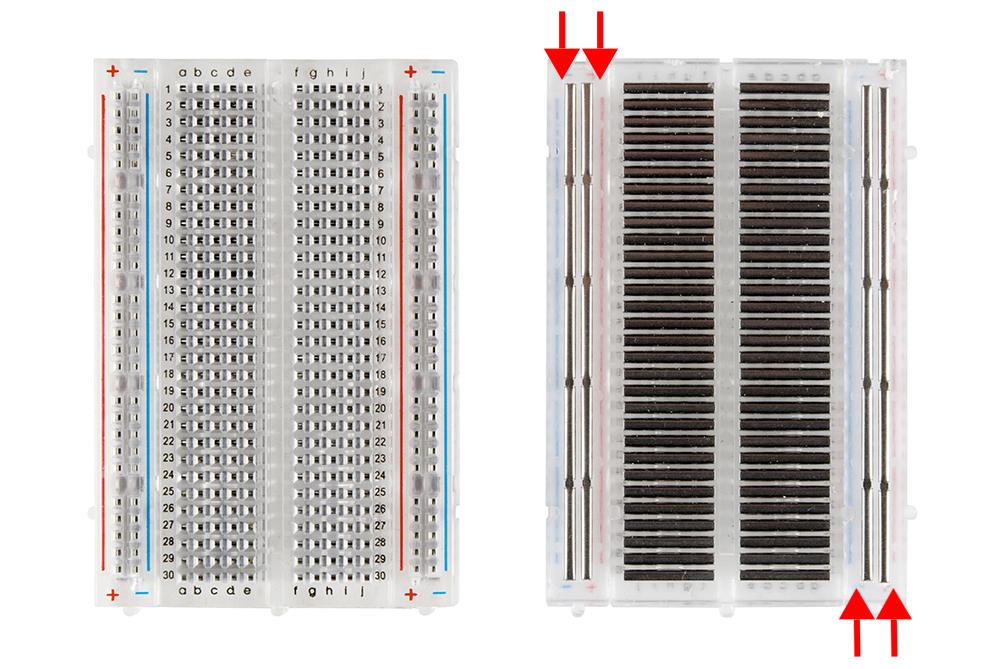
Figure 1. How a breadboard works
All holes that are along the black lines are connected, so anything that is plugged in to each hole will be connected to other holes along the black line.
We will wire up the circuit as follows:
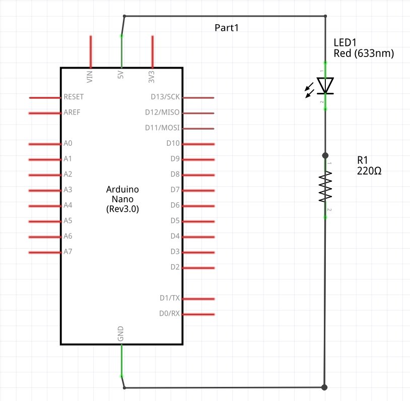
Figure 2. Circuit Diagram
Here L1 is our LED and R1 is an appropriate resistor. The resistor can be in the range of 330 to 1000 Ω depending on how bright you want your resistor to be.
Advice: Always put a resistor in series with your LED! Not doing so runs the risk of burning out the LED.
Note that if you reverse the position of the LED, it will not light up. Current runs in only one direction, and usually components like these will have one of their leads longer than the other. For the resistor, it does not matter which direction you plug it in.
The wiring diagram is provided below:
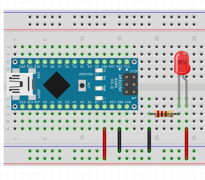
Figure 3. Wiring Diagram
In this wiring diagram, we are lighting up the LED with the power supply.
A breadboard has two power rails that are horizontally connected in the orientation above. The rails in the middle are vertically connected, but not across the trough. The green highlights indicates which two (or more) components are connected.
The program is essentially the same. You might want to change the pin to experiment a little, but upon uploading, you should be able to get it to blink.
FAQ
- Why is one pin lighting up and turning off when I haven't specified in my code?
It might be that the default state of the pin that it isHIGHwhen it is initialized. To solve this, set the pinLOWin setup. Remember that you'll have to put this after you have set the pin as an output. - It still remains on!
The Digispark waits for 5 seconds to determine if you are trying to program it before starting to run it's code. The pins each have defaultHIGHandLOWstates, it might be that the state of the pin you're using is defaultHIGH. - One of the LEDs is super bright!
The wires might be touching. Or the resistor that is in series is too low a value. - It is still not lighting up!
Check that you are connected to the right pin. The pins and their corresponding values are listed in the Chip Capabilities option in the menu on the top right of this page.
What you learned
- How an LED works.
- How a breadboard works.
- How to read a simple circuit diagram.
- How to implement a circuit.
Additional Projects
- Blink two LEDs together.
- Blink two LEDs alternately.
Next Steps
[Lightbeans 2](http://westsideelectronics.com/lightbeans-part-2-sensors-and-libraries/)