UART controlled LCD screen
Creating a simplified LCD interface for simple displays. Communicates over UART!


I really like the ST7735 LCD. It is large enough to display a lot of relevant information at once, but small enough to still be portable. It also has RGB colors, so you can really display some interesting graphs and information with this screen. It is a popular LCD because the communication method is well supported and understood. One LCD is about $2, which really makes it an attractive option as a debugging tool. For example, if your code isn't working, sometimes it might be helpful to print out the internal details to a screen instead of back to a terminal, especially for mobile systems like robots.
One problem with LCDs however, is that they require a high data throughput which can be quite taxing for a microcontroller if it has to do other things like monitor sensor input and communicate with other chips.
Having some familiarity with the ATSAMD10, I wondered if I could put it to use by dedicating one chip for controlling the LCD, and controlling that chip over UART.
UART is pretty simple to implement, especially if you are printing out debugging strings.
Turns out that it was slightly more involved than what I thought, but the benefits are quite great, especially if using a slower but more convenient language like CircuitPython. I previously complained how slow it was to update on the screen. You could see each word being drawn with the CircuitPython implementation, but with the SAMD10, the word appears instantly.
The idea is to have it be a purely UART interface, which results in a total of 4 wires, simplifying a lot of connections (PWR, GND, TX, RX). Unfortunately, I ran into a few unreliability issues with UART because I wasn't using an external clock for the SAMD10, but it turned out after some investigation, that the 8Mhz internal oscillator was not as accurate as the internal 32.768 kHz internal oscillator, and after switching over I was able to obtain consistent results.
I ended up writing my own protocol to call functions and their inputs which are already predefined in the SAMD10 chip. There is a lot you can do with just text, dots and straight lines, so the protocol is quite simple. My program waits for a string of numbers separated by commas and a delimiter. Once the delimiter is detected, the string is decoded into parameters for each function and the buffer is cleared for a new line to be entered.
I picked the SAMD10 chip because I have experience with the chip and have working code for the ST7735 LCD in the ATMEL ASF. It is offered in a QFN form factor, which is a plus as the idea is to build a small and minimal system. It is also a relatively low cost chip, only costing about $1 for single quantities, and it only requires two capacitors to work as a microcontroller. I think this is a fair use of its capabilities.
Increasing speed
Without any performance enhancements, the entire display can update at a rate of about 10Hz. However, the smaller the area that needs to be drawn, the faster the screen can update. For a small region of text, it can update at about 30~50 Hz.
Version 1
Version 1 failed because I did not include a ground pad in my footprint under the ATSAMD10 chip. Previously the design that I copied from worked because there was a ground via under the ATSAMD10 chip, but for this particular application, I had a via for the SWD line under the IC, which definitely ensured that it could not be programmed because it was grounded by the chip.
This version was swiftly abandoned for another version which added a pad under the QFN chip.
Version 2
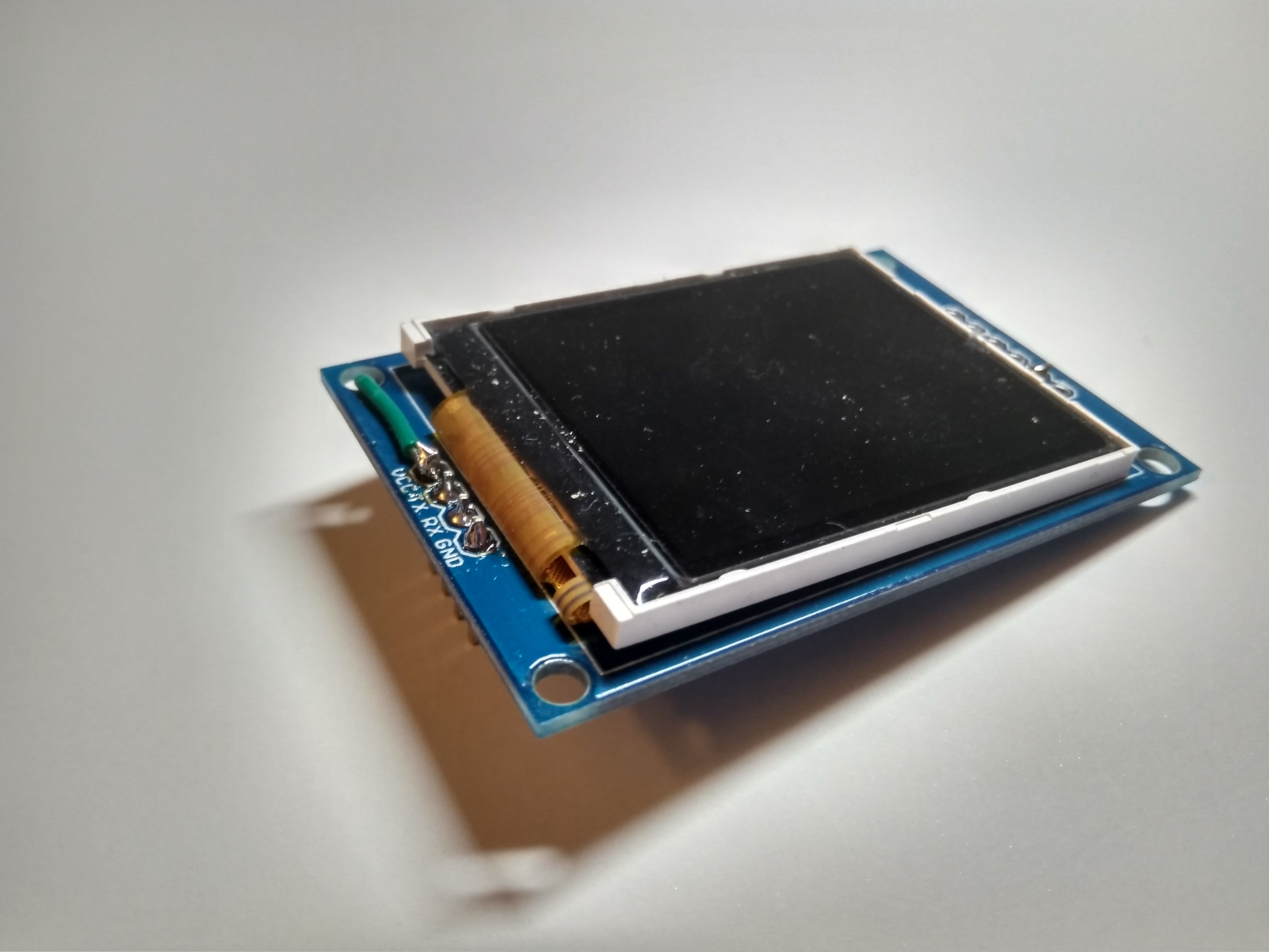
Version 2 partially worked, but it required a few hacks. The transistor used to power the screen was not working due to my design fault of using a P-Channel MOSFET on the low side of the load. I also wanted it permanently on, so I removed it and soldered the pads together.
It did not work during the first programming although it was updating the screen and sending a "Hello World!" message over USART correctly. I decided to add some response code so I could see what I sent over USART... and it worked.
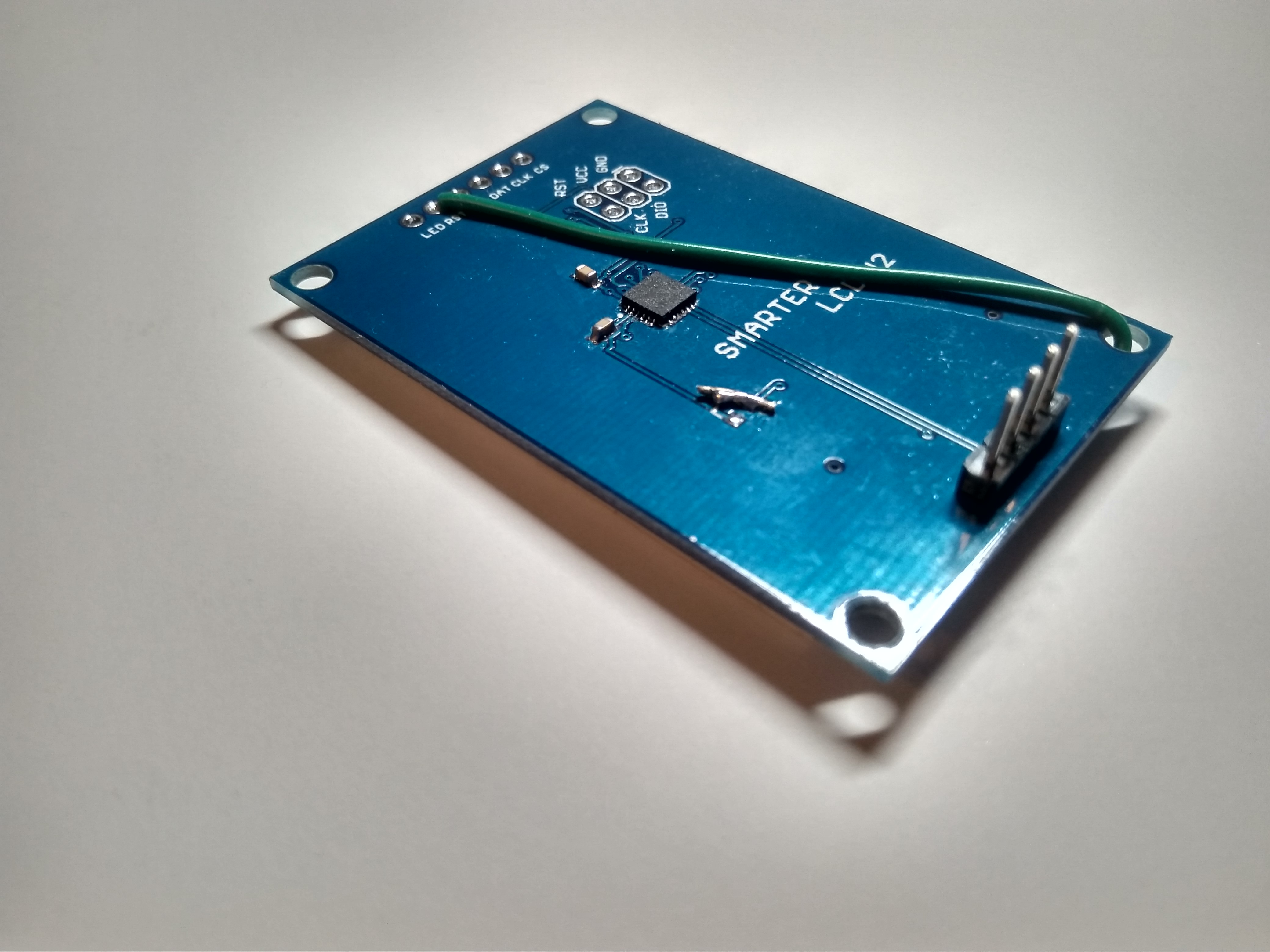
The RESET pin also had to be pulled up in order for the screen to work, and so I had to solder a wire from the RESET pin to the VCC pin.
I noticed some strange behavior from the LCD when interacting with the STM32, but it turns out that I have to properly count the number of characters being sent otherwise it will send some garbage characters after the delimiter.
Usage
Once the parts have been soldered, program the board using code from Github. Note that if you don't have pogo pins, it might be best to program the board first before soldering on the LCD.