Old Alarm Teardown and Buildup

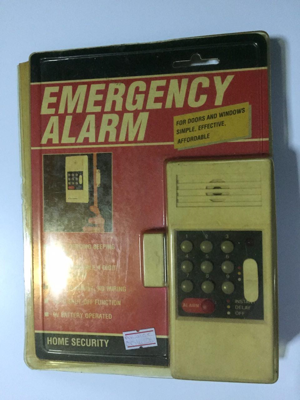
I had one of these lying around the house. It was bought for the windows and doors, but it was never used at my place.
Operation
The white package next to the alarm is a magnet, so this indicates that the alarm is operated by a reed-switch. When the door is opened, the magnet will move further away from the alarm. The changing magnetic field is detected by the alarm, and it starts a countdown. When the password is typed in, the countdown stops. If it is not typed in before the countdown completes, the alarm will buzz.
Opening
It did not have any sort of telecommunication equipment so I assumed that it was a simple buzzer with a slightly more complex password capabilities. The plastic cover was attached by a hook on one end and a screw on the other. The inside was not reinforced, so the alarm could have easily been defeated by prying it open, and cutting the power or the buzzer.

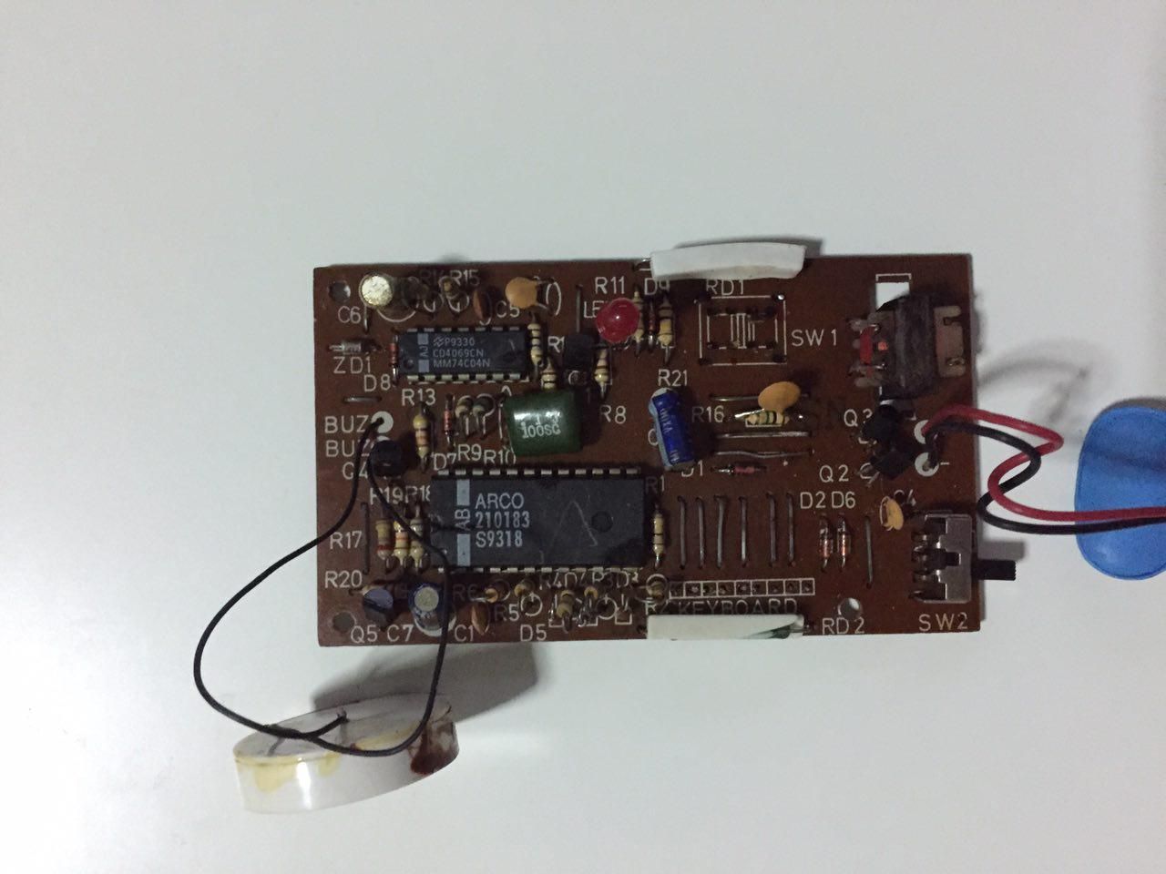
The components were mostly through hole and notice that it is a one-sided PCB, with the wires on the bottom right being the top bridge of the traces below for the keyboard. I anticipate being able to extract some of these parts for use, however, the chips themselves are not of much use, since they are more than 10 years old and I was unable to find any reference to the markings on these chips.
The keyboard itself has quite an interesting design:
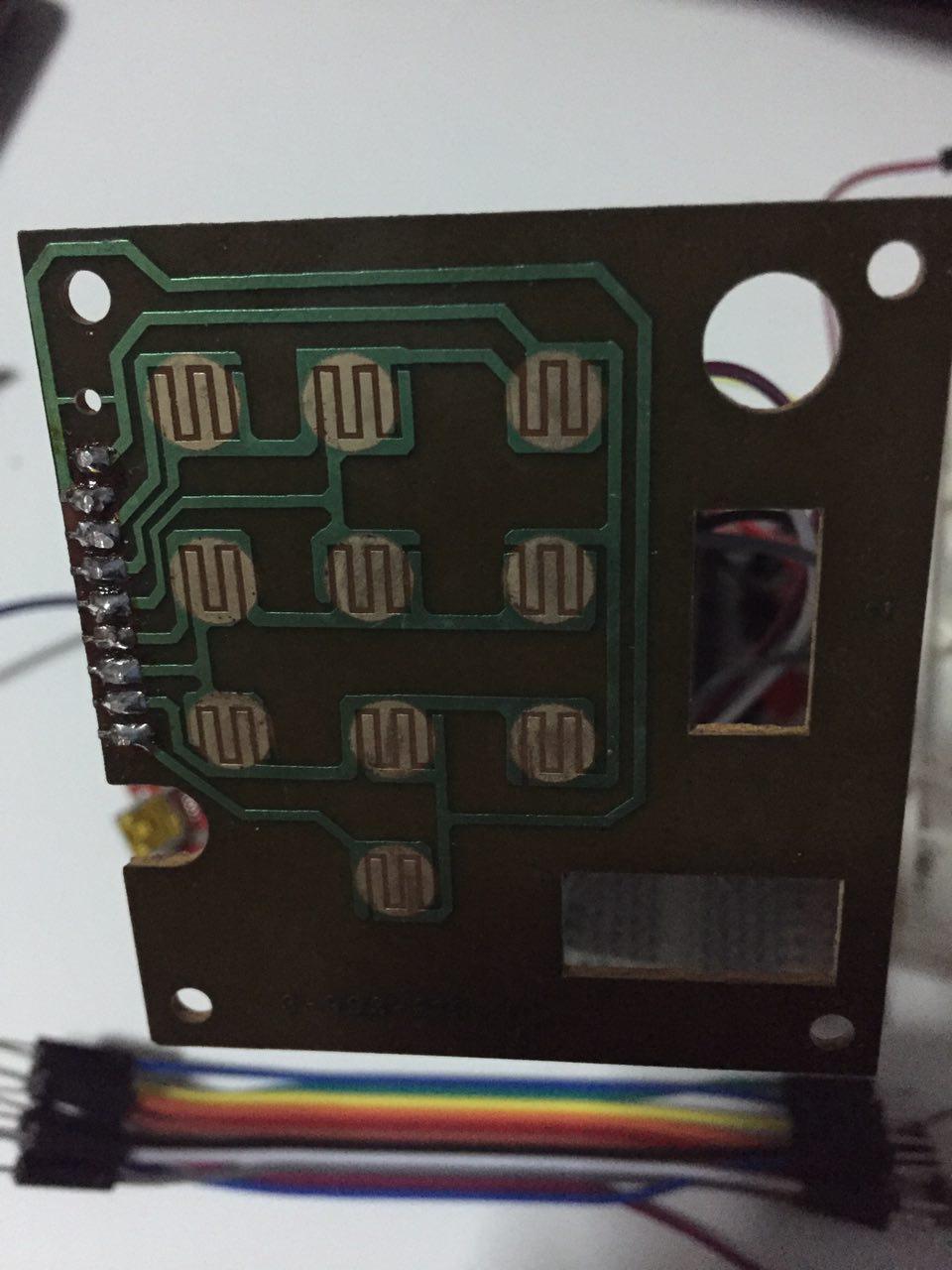
As you can see, and after a moment of tracing, the buttons themselves are not serial, and a pin can have up to three switches connected to it. There are two ways this could have worked, and I suspect that each row was turned on momentarily to detect if a button was being pressed, as suggested in Lucid Science. This would be done quickly, and a decent detection can be made. Alternatively, 3 levels of voltage can be applied to input pins, and this cuts down on the total number of pins (4) needed to detect the buttons being pressed: 3 Analog pins and 1 Digital pin.
Another way is to use voltage dividers to supply different voltages to the rails, and then using a single voltage divider to determine which button is being pressed. However, as there is a lot of noise when these buttons are pressed, precise determination of whether a button is pressed is not easy, as the differences in voltages might be about 0.2V apart, perfectly within the fluctuation ranges when buttons are pressed.
After some experimentation, I decided that I liked using 3 voltage levels to detect button presses, because it was more precise.
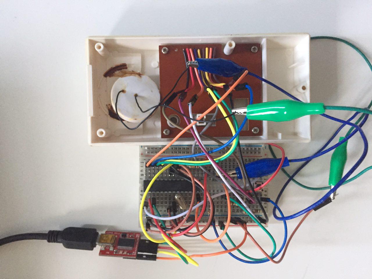
I decided to wire it up and I had to add a little debounce code to ensure that all the buttons worked as expected
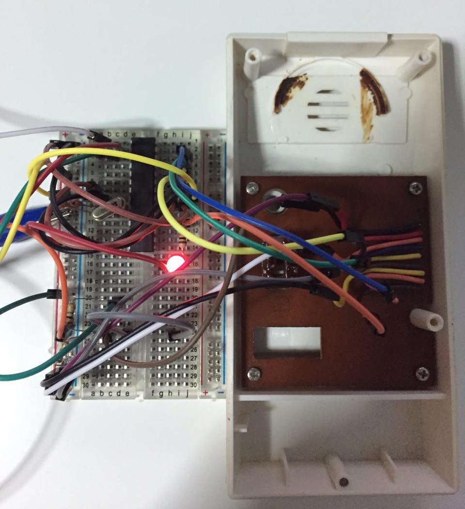
That's an ATMEGA328P aka the chip of Arduino UNO fame. I then used it with a voltage divider to supply 1.3V, 2.6V, and 0V to the circuit for detection. When not pressed, the pins are drawn up to 5V.
Next I implemented some music to the device, just for fun. Now pressing the buttons are much more entertaining.
Once I was reasonably sure that my circuit worked, I transferred it to a stripboard. This was quite frustrating because I would solder a wire in a wrong place. There are some solutions to reducing the pain of transferring a circuit from a breadboard to a stripboard, such as Adafruit's Perma-Proto Board and the Plusboard.