Design Analysis - Simple Clock
A simple clock that you can find anywhere for cheap. I take a close look at what makes it tick.

You see these clocks everywhere. They hang on walls of kitchens and offices, quietly ticking away, keeping count of the time left in the day. One of these clocks in my house recently failed so I decided to take a closer look at the inner mechanisms of a clock.
If you think about it, a clock is not a simple task, especially with how it is presented: three rotating pointers on a single shaft, all turning at different speeds. If you directly drive one pointer, say with a motor, how would you put another axis of rotation through the same vector? The solution, as it turns out, is to just wrap shafts around each other.
Mechanism
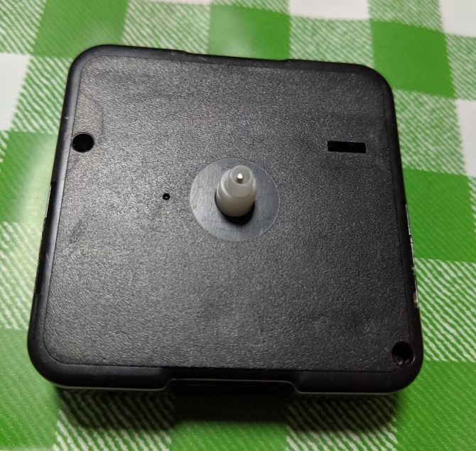
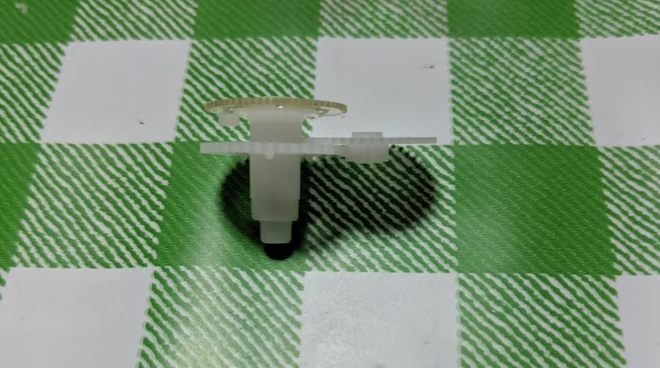
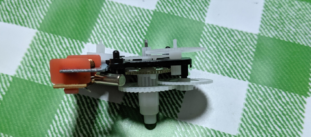
Here you can see the central shaft, the second hand, inside two shafts, of which there is a step. This helps to locate the hands, which are press-fitted onto each plastic shaft. The hands themselves are made of thinly stamped aluminum. Interestingly enough, while burr from stamping the aluminum is considered a defect from the stamping process, for the hands, this actually appears to be an intentional design feature because it allows a stronger fit of the hand onto the shaft because the contact area is made larger.
Have you ever wondered how many internal clocks are needed to keep the rotation of the three hands to be consistent?
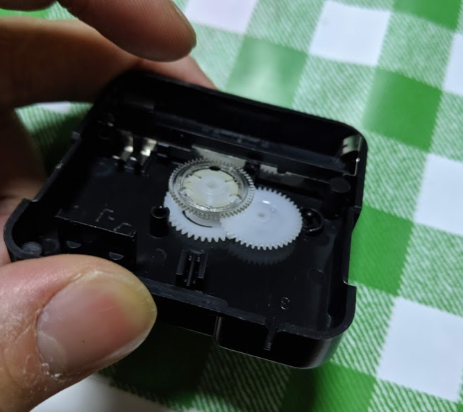
Opening up the back of the clock reveals the mechanism. The transparent gear sits on top of the white gear below. These two gears can rotate independently. The other white gear on the right side couples both gears. It is not clear in this image, but this gear is stepped. This means that there are actually two gears here, a smaller one below (not shown, and a larger one.
Imagine the translucent gear at the topmost part of this picture was rotating. It drives the gear on the right side at a slower rate, which in turn drives the bottom-most white gear. All the shafts fit onto the stepped series of white cylinders.
If you ever wondered how clocks keep their hour and minute hands synchronized, its purely mechanical. Only the second hand is driven directly. All other hands are driven via gear reduction.
This makes sense because the rate of rotation of the hour hand is directly proportional to the rate of rotation of the minute hand, which is turn is directly proportional to the rate of rotation of the second hand so we would expect to find some coupling mechanism.
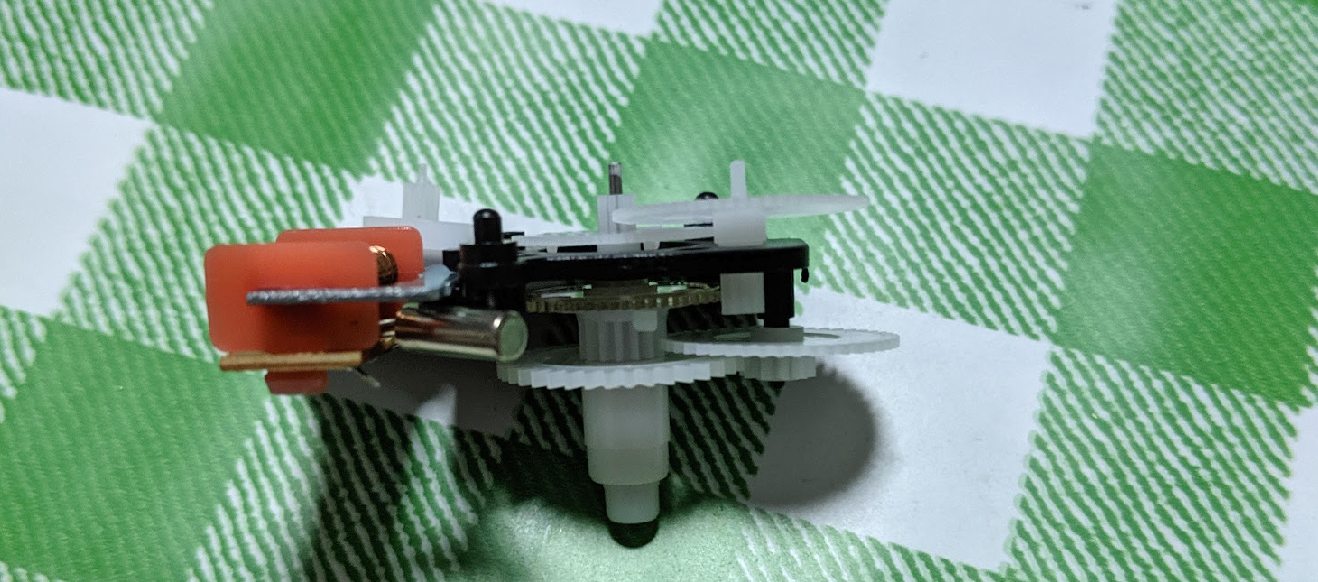
Here we see yet other coupling gear on the top right, where it connects the gear with the silver shaft to the translucent gear. This entire mechanism is driven by a rather ingenious circuit.
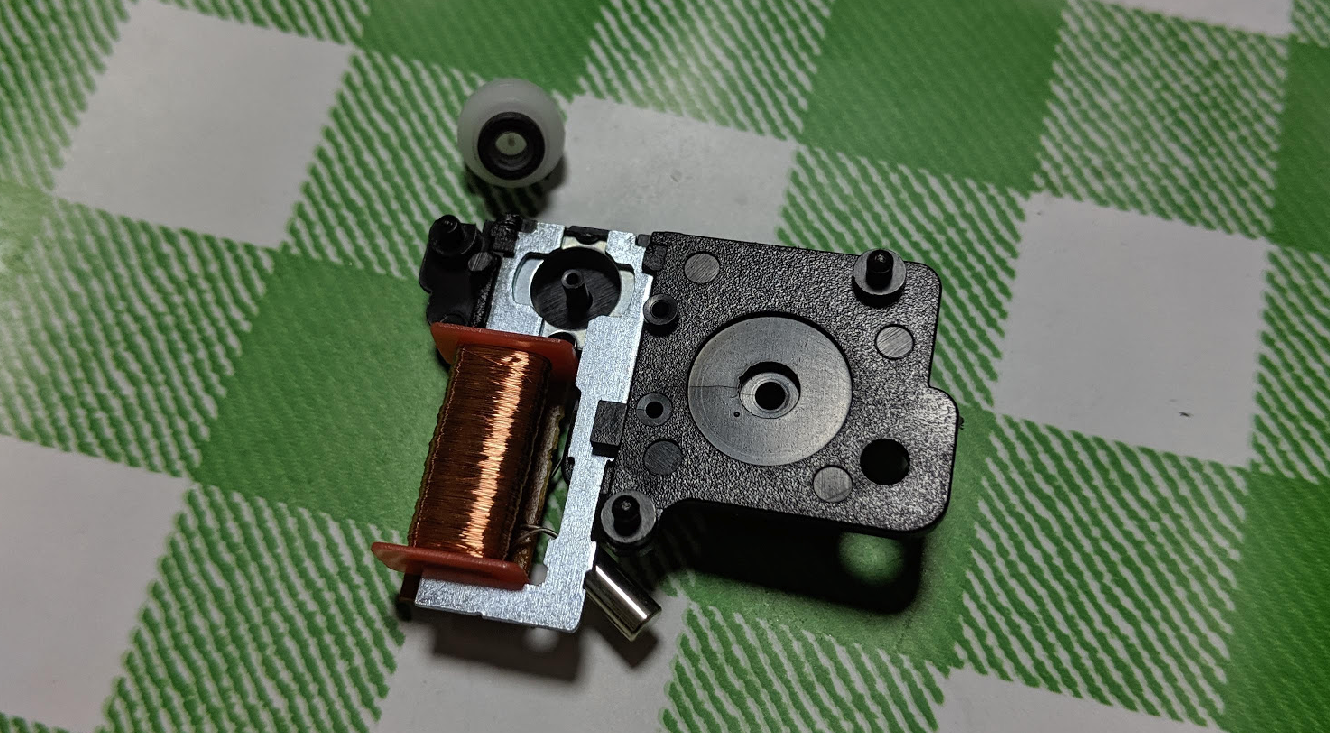
On the bottom of the metal piece is a circuit board with an epoxied IC and metal contacts for the battery. It is not very exciting except for seeing how thin the wires on the orange inductor are. The real magic is how the gear is driven. I determined by hand that the black ring on the bottom of the white cylinder is a magnet, with poles on the left and right side (as far as sides on a circle can be determined).
When the inductor is powered, it generates a magnetic field in the metal, this causes the gear to rotate because of magnetic attraction. I'm not entirely sure why the rotation is in one direction, but I think it has to do with the induced fields not being equally strong (one end is further from the end of the inductor compared to the other end), so the magnet is inclined to rotate in one direction. On the next 'tick', the current in the inductor changes direction, and the magnet rotates again. This is essentially a poor-man's Stepper Motor.
Now I think the next part is the reason why this mechanism can run on years off one AA battery: the magnet actually levitates off the support. This means that the friction encountered is very low, and since no brushes are required, the 'motor' will not wear out. This is aided by two locating mechanisms, the black shaft to hold the bearing up, and the thin silver shaft from the white gear that fits into the black support shaft. The magnet is attracted to the metal around it, so it never fully sits on the black shaft, allowing it to 'levitate'. By eliminating friction here, the current required to run this mechanism is a lot less.
Housing
The case uses a snap-fit mechanism and plenty of locators to hold the many gears in place. One interesting observation I made is that sometimes there would be locators around part of the gears as well, which is perhaps to help in assembly. The parts appear to be injection-molded ABS. It is held to the clock face with by snap fits as well.
Electronics
No significant electronics to speak of. There is an epoxy blob on the small PCB hidden under the inductor with what looks like a 32.687kHz crystal soldered on.