C005 Cheap Delay Timer
Need to turn off your circuit for some time but don't want to fiddle with a microcontroller/sleep settings? How about using a delay timer board for 10 cents?

I recently got very interested in controlling the amount of power my boards use because between transmitting data and using battery powered devices, there isn't a whole lot of energy to spare if you don't want to be tied to a wall wart.
Adafruit and Sparkfun both sell the TPL5110 breakout boards that essentially act as delay switches that start a timer when a switch closes. The system shuts off the power by sending a signal to the trigger pin, which opens the circuit. When the period is up, the switch will open again. However, because it is a little expensive for me, I was looking around for alternatives, and this little board caught my eye:
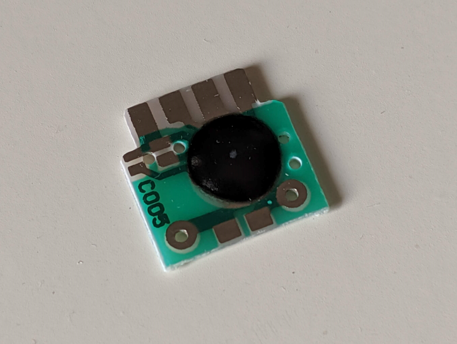
This is advertised as delay timing chip/delay chip/Trigger delay IC/2s-1000h timing IC. It is also known as the C005 delay chip due to the markings on the side. It is literally a piece of PCB with an epoxy glob. It also costs about 50 times less than an equivalent board from Adafruit or Sparkfun. Unfortunately, all of the descriptions online appear to be a copy-paste of the original instructions, which is a set of gibberish sentences in English:
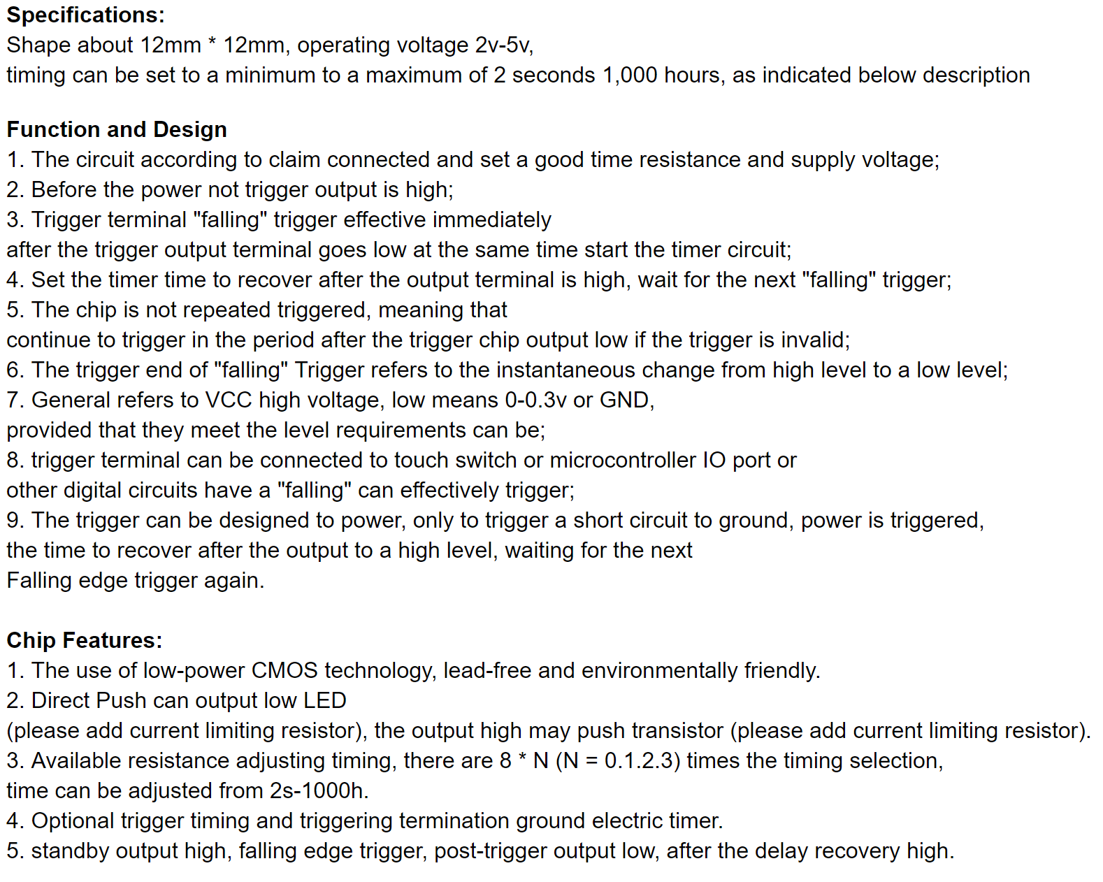
Translation
Specifications
The size of the board is 12mm x 12mm, with an operating voltage of 2v to 5v. The timing that the Output is low for can be set to a minimum of 2 seconds and a maximum of 1000 hours.
Function
- While the trigger is not activated the output is high. The trigger can be activated by sending a falling signal to the trigger pin.
- Once the trigger is set by an external controller, the output goes low. An internal timer starts as well.
- Once the timer completes, the output will reset and the chip will wait for the next falling signal.
- The chip is not repeatedly triggered, meaning that in the time between it is triggered and resets, it will not respond or keep track of any other falling signals from the external controller.
- The trigger can be tied to the output as a short detector, so it will cut off the power when there is a short circuit to ground. It will then attempt to reset the power after a short period of time. (a pretty nifty feature!)
Features
- Uses CMOS and is lead free (this is debatable)
- It can be used to power a LED or may be used to control a transistor that can be used as a switch for high-power circuits. Current limiting resistors are required.
- The timing can be changed by adjusting the resistance, and there are prescalers available to further change the timing.
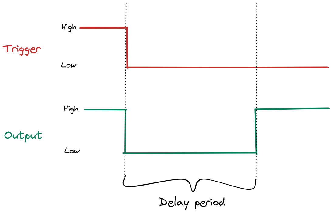
Diagram
Testing
After some experimentation with the C005 IC, I figured out that when Trigger is pulled to LOW, the falling edge causes the OUT pin to go LOW for a specific period of time before going back to its default state of HIGH.
This is a one shot timer because it requires an external input for it to change state.
For a low power circuit, the ground can be tied to the OUT pin. This way the delay works as a low side switch and controls power to the circuit through the connection to ground. If an external trigger is activated, the circuit will turn on and process the event for a predetermined length of time before it turns off.
Another way this can be used is to tie the output to a transistor that acts as a high power switch. Let's say I want a circuit to turn off for an hour each time. I will first pick out a resistor that gives me an hour from the timing table, then I will then program my microcontroller to send a signal to the trigger pin when it is done. This will cause the output to go low for the specified period of time (an hour) before it automatically goes back to high again.
The OUT pin is not able to source a significant amount of current, so it is not possible to run a circuit directly from the OUT pin unless your current requirements are very small. Holding the Trigger down does not automatically trigger the output again, as the condition for toggling the OUT pin is a falling edge on the Trigger pin.
The nice thing about this chip is that the solder pads are spaced 0.1 in apart, so they can be soldered to standard headers. Another benefit of this IC is that it can also be used as a timer for a much longer period than the TPL5110. While it definitely does take up more space, it is 10x cheaper than a TPL5110 in single quantities, costing about \$0.15. I measured the timing period to be stable to a few milliseconds.
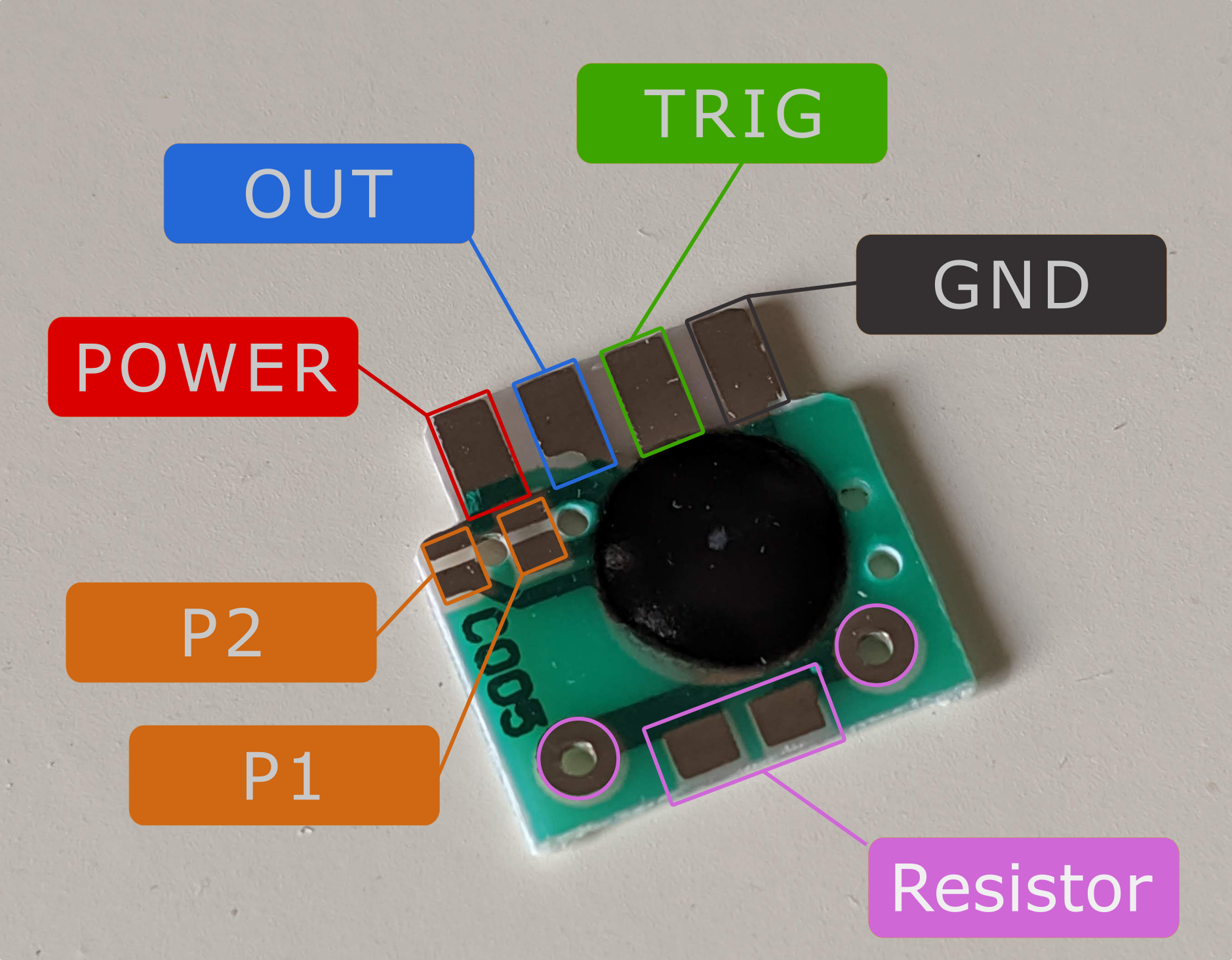
Connecting the circuit

This chip takes in voltages from 2V to 5V. You will need to solder a resistor to set the timer.
P1 and P2 are primarily used to extend the time. By shorting P1, you extend the time by 8 times, by shorting P2, you extend the time by 64 times. Shorting both yields a time extension of 512 times.
By placing either a SMD resistor or a through-hole resistor on the board, the time can be varied as seen in the reference table at the bottom of the post. The timing is also dependent on the voltage that is applied to the circuit. Alternatively, you can also add a trimpot to vary the delay.
For stability, a pull-up resistor can be added to the trigger pin. Do note that the output pin appears to be capable of sinking up to 30mA and is not a full power switch. You will need to add the power circuitry yourself if you intend to use this timer IC for high powered operations.
Steps
- Select a resistor and solder it in
- Connect power and ground
- Tie the trigger pin to an external device or switch
- Tie the output pin to the circuit to be powered
Power consumption
This chip/board draws about 100uA when active (when it is keeping time, OUT is low). It draws about 1uA when it is sleeping. It does not provide much benefit compared to sleep modes, which for the nRF52840 or ESP32, draws about a few uA when they are sleeping. However, if we are considering a more complex circuit like a board with other components that are also drawing power, then maybe this chip has a role in being the middleman for power management. This can also be useful in circuits that need to be timed but don't have a microcontroller, or retrofitting existing circuits to have sleep features.
Reference Table
These times apply when both P1 and P2 are not shorted.
| Resistance | Timing under 3V (s) | Timing under 4.5V (s) |
|---|---|---|
| 10K | 5.8 | 4.8 |
| 20K | 8.9 | 8 |
| 30K | 12.1 | 11.4 |
| 51K | 19.2 | 18 |
| 75K | 26.5 | 25 |
| 100K | 34 | 32 |
| 150K | 49 | 46 |
| 200K | 65 | 60 |
| 240K | 78 | 74 |
| 300K | 96 | 92 |
| 390K | 123 | 119 |
| 510K | 155 | 150 |
| 560K | 175 | 168 |
| 620K | 199 | 187 |
| 750K | 230 | 222 |
| 820K | 255 | 246 |
| 1M | 330 | 291 |
| 1.5M | 383 | 432 |
| 2M | 598 | 568 |
| 3M | 762 | 762 |
| 4.7M | 1425 | 1165 |
| 5.1M | 1631 | 1331 |
| 10M | 2921 | 2621 |
| 15M | 4394 | 3813 |
| 20M | 5160 | 4660 |
| 22M | 7052 | 6452 |