Building an Arduino compatible HM-11 Bluetooth board


After messing around with the nRF52 for a little while, one day I wondered if there was a cheaper option for bluetooth modules, because all I really wanted was the Bluetooth from the nRF52. It took awhile to look, but I was not disappointed. I found the CC2541.
Introduction
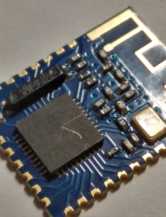
HM-11 modules have been floating around for a very long time. Their latest claim to fame is their enlistment as credit card skimmers, as documented on Sparkfun's investigation. I encourage you to read it, it is quite detailed and fascinating.
After shopping around, I decided that I liked the JDY-08 version the best. While it might be a little fiddly, it is quite tiny and good for placing on boards. This cost of a module is $1.60, which makes it an extremely attractive option compared to the nRF52, even when the cost of an additional MCU is taken into account.
I find myself coming to appreciate the ATMEGA328P more and more. This is the chip that is used in the ubiquitous Arduino Uno. I used to look down on it, because I thought it was too simple, too small, too slow. However after some time working with other chips, I realise that when something isn't working, I always reach for my Arduino Uno. A lot of code is written for this particular framework, and it is easier to use a platform you know that simply works.
While the TI chip can be used as an MCU as well, it requires the purchase of a $50 debugger and it assumes that you use a $3000 IDE, so a secondary MCU such as a ATMEGA328P or a SAMD21 is required unless you already have the requisite tools.
Design
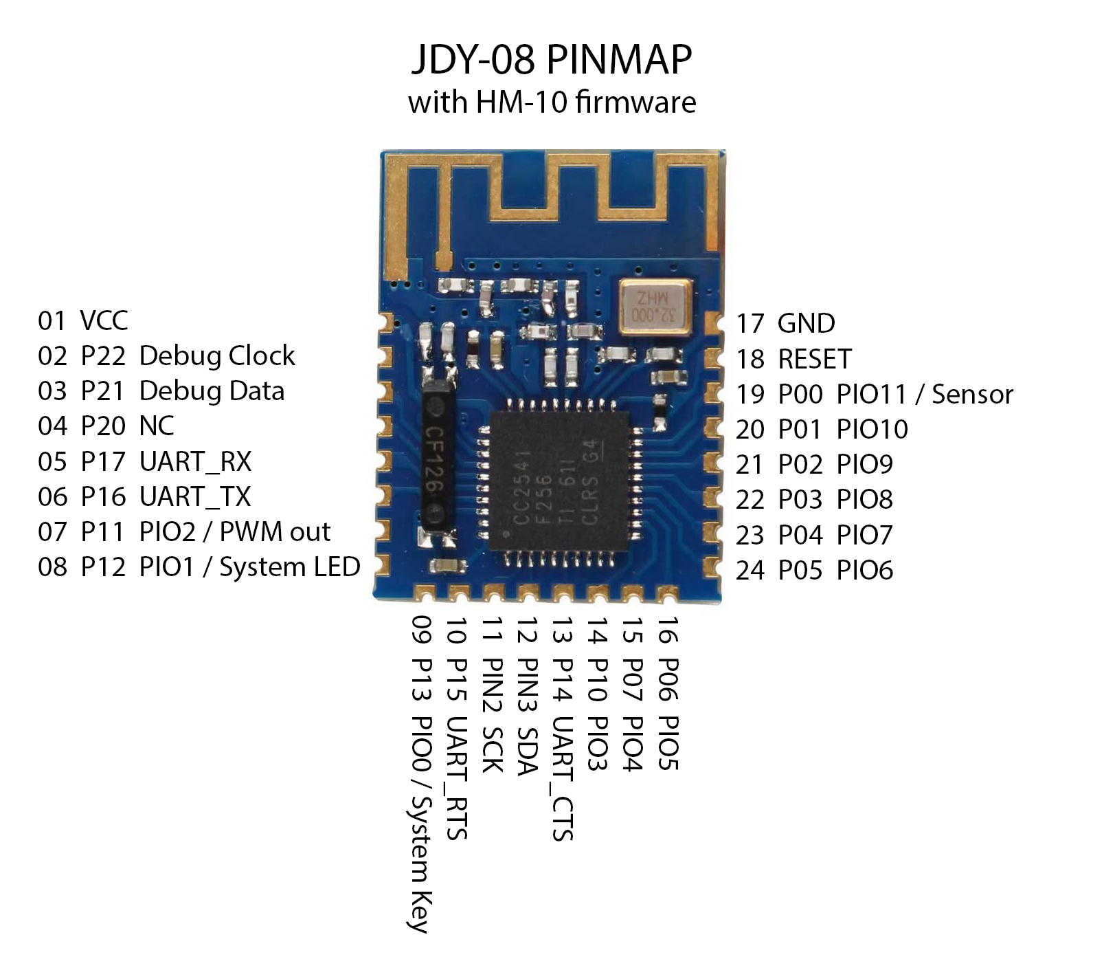
All pins on the JDY-08 are 3.3V, which means that it would be best to clock an Arduino at 3.3V so that only one power source is required. This means that the frequency is limited to 8 ~ 12Mhz, the standard being 8Mhz, while Adafruit has a version that is clocked at 12Mhz.
The MCU can be the ATMEGA328P so as to reduce any potential problems of the code not being compatible with a particular architecture. An alternative could be the SAMD21, with the advantage being that the SAMD21 does not need additional FTDI hardware to communicate with the computer. However, it is about $1 more expensive, negligible compared to the total cost of assembling the board.
A more radical design would eschew the USB circuitry altogether and just use the Bluetooth board to communicate and upgrade the firmware. The Lightlog is one example.
I believe that it can be built as a transparent serial bridge (slave mode) and this will allow uploading of code wirelessly. This is pretty exciting because this means that the board can drop a USB interface. Plus uploading code wirelessly is undeniably cool.
Build
Trying to solder to the tiny 0.65mm pads was a tricky business, and I decided to take the easy way out: design a breakout board. I initially wanted to break out all the pins, but I realised that it was not necessary since all I really want is to use the BLE board as a communication node. It is sometimes not the best idea to break out all the pins, because it will expand the size of the board while adding very little functionality.
I found some existing work my platisd, and updated it a little to reduce the size (OSHpark charges by area), and to add a capacitor on the power lines. Reducing the area also removed the ground plane below the antenna, which should give these modules a slightly better range.
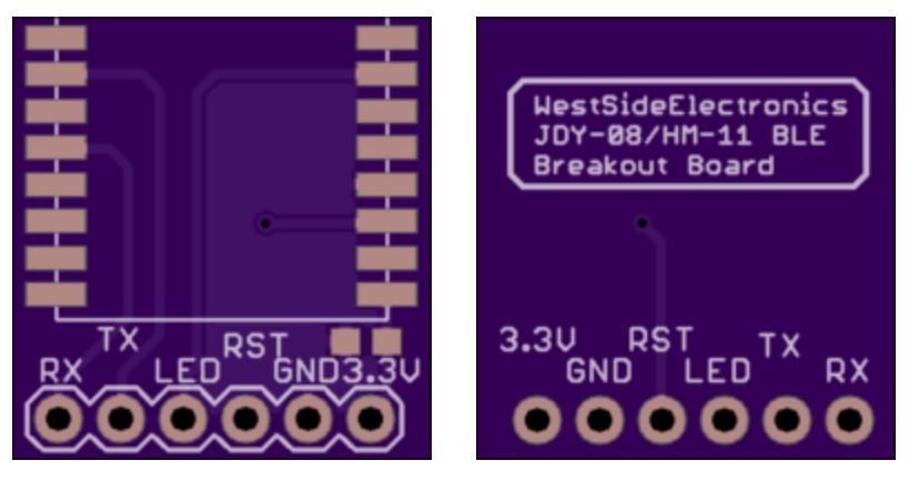
This is my work on Github:
https://github.com/benlhy/HM-11_breakout
Next Steps
Getting it to work with Arduino and Android!
GHOST_URL/arduino-android-data-streaming-jdy-08/