Breadboarding (2)

We will blink an LED again, except this time we will move it to to the breadboard. The difference is that we are connecting an external circuit to our microcontroller by giving one of the pins an output signal (much like how everything is run).
This is important for two reasons: the signal must be of the right form, and it must be of the right magnitude. Some components might be expecting an electrical signal of a specific order, and when this is incorrect, we get data corruption. Too high a magnitude can burn out a component, so we have to ensure that both the signal type and magnitude are correct.
Luckily for us, a Light Emitting Diode (LED) is a relatively simple component. It takes an input voltage and converts it to light. However, it can only take up to a certain voltage before it burns out. We don't want to burn out our LED, so how should we wire it?
The simplest way to do so is to put a resistor in series with our LED. The resistor helps to split up the voltage and prevents us from supplying a voltage that is too high to our LED. For a 5V supply, any resistor from 330 to 1kΩ is suitable. The wires coming out of the LED are known as leads, and the longer lead always goes to the higher voltage, and in our case, the pin that we are using it on.
WARNING: Not connecting a resistor in series with your LED will cause it to burn out or in rare cases, explode. So remember: ALWAYS connect a resistor in series with the LED.
To do this, we will use a breadboard. A breadboard is super useful for prototyping designs and circuits because you can connect components electrically without having to solder them together.
We will wire up the circuit as follows:
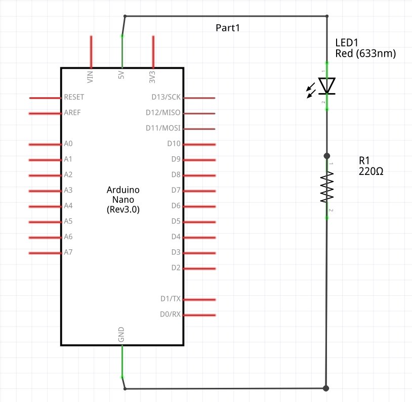
Figure 1. Circuit Diagram
Reading circuit diagrams is a good skill to develop because more advanced circuits may only be represented as a circuit diagram. Here L1 is our LED and R1 is an appropriate resistor. This can be in the range of 330 to 1000 Ω depending on how bright you want your resistor to be.
Advice: Always put a resistor in series with your LED! Not doing so runs the risk of burning out the LED.
Note that if you reverse the position of the LED, it will not light up. Current runs in only one direction, and usually components like these will have one of their leads longer than the other. For the resistor, it does not matter which direction
The wiring diagram is provided below:
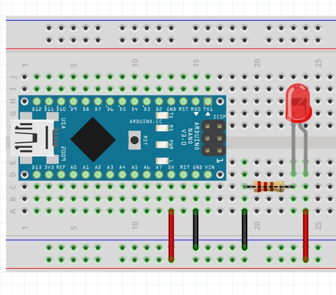
Figure 2. Wiring Diagram
A breadboard has two power rails that are horizontally connected in the orientation above. The rails in the middle are vertically connected, but not across the trough. The green highlights indicates which two (or more) components are connected.
The program is essentially the same. You might want to change the pin to experiment a little, but upon uploading, you should be able to get it to blink.
FAQ
- Why is one pin lighting up and turning off when I haven't specified in my code?
It might be that the default state of the pin that it isHIGHwhen it is initialized. To solve this, set the pinLOWin setup. Remember that you'll have to put this after you have set the pin as an output. - It still remains on!
The Digispark waits for 5 seconds to determine if you are trying to program it before starting to run it's code. The pins each have defaultHIGHandLOWstates, it might be that the state of the pin you're using is defaultHIGH. - One of the LEDs is super bright!
The wires might be touching. Or the resistor that is in series is too low a value. - It is still not lighting up!
Check that you are connected to the right pin. The pins and their corresponding values are listed in the Chip Capabilities option in the menu on the top right of this page.
What you learned
- How an LED works.
- How a breadboard works.
- How to read a simple circuit diagram.
- How to implement a circuit.
Additional Projects
- Blink two LEDs together.
- Blink two LEDs alternately.