Action, Sensor Reaction (4)

Often when we build devices we want them to react to the external environment. This means we have to implement some sort of sensor to detect the changes.
In this case we'll build a light detector that brightens according to how much shade is thrown upon it.
We'll need to use a light sensor. This can either be a photo-transistor or a Light Dependent Resistor (LDR). The difference is that a photo-transistor is more reactive in certain levels of brightness closer to the human eye while an LDR has a linear relationship with the absolute brightness of an environment. An LDR is also bipolar, which means that it doesn't matter which lead you plug into ground and positive, while a photo-transistor has polarity like an LED.
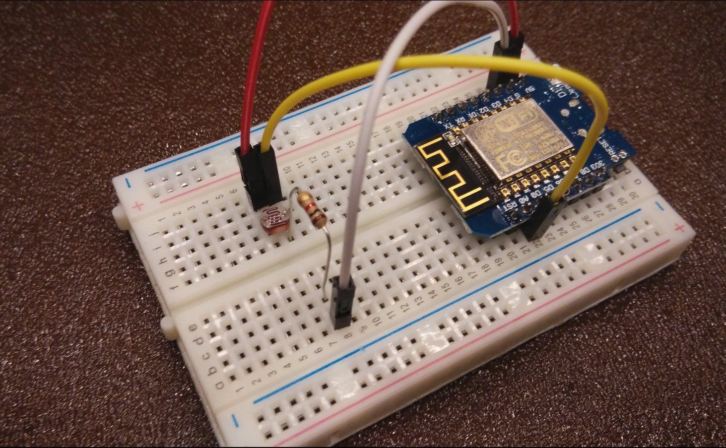
The brighter the room, the smaller the resistance across the LDR and hence a smaller voltage will be passed through it. Let's experiment with this by hooking it up as follows:
 Figure 1. Wiring schematic
This circuit is a potential divider circuit that breaks up the voltage across the resistors in proportion to the magnitude of the resistances. The pin at A0 tells us the voltage after the LDR. Under brighter conditions, the resistance across the LDR falls and hence the voltage across the LDR falls accordingly and A0 reads a higher value.
If you flipped the position of the resistor and the LDR, which you can do by flipping the 5V and GND pins as seen below:
The signal to A0 will then be flipped. It will read a low value in a bright setting, and a high value in a dark setting. Hence being able to estimate or determine voltages is very useful in predicting outputs and programming accordingly
Note that you'll have to scale depending on the brightness of the place you are using the circuit in. To get greater sensitivity in brighter settings, decrease the resistance in series with the LDR, and vice versa in darker settings.
Why are we using an analog input? Well since our other pins are digital, they can only sense if an input signal is HIGH or LOW. That is not in general very useful to us.
Programming
As usual we want to define our pins:
pinMode(A0,INPUT);
Now we want to use the Serial library to learn what our little sensor is detecting(note that this is not possible for the Digispark). A library in general refers to a set of programs or functions stored externally in a file, which you can use in your own program without having to write the programs or functions yourself.
This is sort of like visiting a library and pulling a book out to quote a line or copy an equation. So instead of having to write that entire book yourself, you can simply refer to the quoted material as "Book of Math, page 4, line 6". It is very convenient and this process makes for a cleaner program.
By default the Serial library is included, but not all libraries are, so sometimes we will have to define libraries. We'll not worry about that now, instead, within setup include:
Serial.begin(9600);
This sets up serial communications and the speed at which signals are sent is defined within the brackets. Now open the serial window by clicking the button at the top right corner of your Arduino program and check the 'baud rate' is the same as what you have defined. Sometimes if you receive gibberish in the Serial window, it is usually because the baud rates are different.
I wish to set up a constant to store my read values:
int light_level = 0;
Now let's read our values and print them every second:
light_level = analogRead(A0);
Serial.println(light_level);
Serial.println("Println in action!");
Serial.print(light_level);
Serial.print("Print in action!");
delay(1000);
What do you notice? With println the output is printed on each new line while print prints on the same line. This is useful for formatting the output on the serial and other interfaces
Now if you shade the LDR, the values should drop and when you put it under light, the values should go back up.
Now we want to do something to this data we are getting. Looking back on our original LED program, can you come up with the final form of this project?
We want to write this value to the LED. Analog inputs are scaled from 0 to 1024, but our LED only scales from 0 to 255 so we need to modify this a little:
LED_value = light_level/1024 * 255;
However this only works if you have set up your LED such that the range is the full range. However my setup only went up to a maximum of 300, so the input was simply equated to the output.
LED_value = light_level;
To make it a little more interesting let's make our LED light up when it is dark:
LED_value = 300 - light_level;
The value of 300 was determined through a little trial and error. This is the largest value you should be able to read in your environment and setup. If the value you determined is too low, a negative value will be given to the LED and this essentially means that it counts backwards from 255, so you might actually see your LED suddenly become brighter after dimming!
Remember to define any new constants you use!
Sketch
int LED_value;
int light_level;
void setup()
{
    Serial.begin(9600);
    pinMode(A0,INPUT);
    pinMode(D1,OUTPUT);
}

void loop()
{
    light_level = analogRead(A1);
    Serial.println(light_level);
    LED_value = 300 - light_level;
    analogWrite(D1,LED_value);
    delay(10);
}
What you learned
- Analog inputs.
- Using sensors to drive outputs.